Table of Contents

EVO: Engine Mechanicals - Sub-04P
Valve Train Geometry
Every thing we do in the valve train effects the geometry and that effects net valve lift among other things like seal and guide wear. Sometimes the push rod length can be used to correct this and other times not. Much of this is “best guess” math and with hydraulic lifters many times this is good enough as they will self adjust to a point as long as the modifications are not too wild. 1)
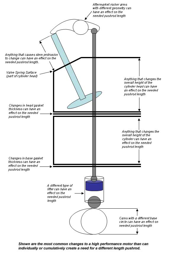
- Lots of things are involved in the math.
- Valve Stem protrusion or length from the spring seat to the valve tip
- Cylinder height (or length if you will)
- Cylinder head deck to rocker stand seat
- Rocker arm type and brand (are they accurate?) Roller Tip or non roller.
- Rocker arm ratio
- Head gaskets
- Base gaskets
- Tappets (Stock hydraulic, Solid, Hydro Solid)
- Camshaft base circle
 2)
2)
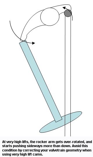
Each end of the rocker arm travels in an arc. To the extent that arc is over or under rotated, the contact point moves that much more sideways and less vertically, costing you lift and increasing the valve side loading (thus accelerating wear). You want both the valve travel and the pushrod travel centered in the arc, such that at half lift, you have a 90° angle between the valve stem and a line drawn between the valve tip and the center of the rocker shaft. You want a similar 90° angle on the other side as well. 3)
 4)
4)
As you get into high lifts, this starts becoming a concern (at valve lifts of .575“ and higher). Essentially what happens is that as the valve gets pushed open farther and farther, the rocker tip starts moving sideways on the valve tip more than pushing down. You also start getting the same effect on the pushrod side of the rocker arm, where additional lift starts causing a lot of sideways motion because you're not well centered in the arc. The corrective action for this problem is to extend the valve stem protrusion such that the tip of the valve is raised. You essentially want to raise the valve stem protrusion by about half the amount you increase the valve lift, the idea being to keep a 90 degree angle between the valve stem and a line drawn between the valve tip and the center of the rocker shaft when at half lift. This gives maximum lift with the least amount of side loading possible. Often times the valve stem protrusion needs to be raised anyway when using very high lifts just to get enough valve spring travel. 5)
HEAD DECK:
The SE head is just a stock head that's been molested, by decking the bejeezus out of it (for more compression) and also by cutting down the valve spring pockets (for taller springs & more travel). Ports and valve sizes are completely stock, and the flow is identical. Both of those changes cause issues (reduced piston to valve clearance, manifold fit problems, pushrod length problems, and a thin port roof that compromises your ability to port it). There are other, better ways to get more compression and more valve travel that don't cause problems and they have to be compensated for. 6)
Pushrod Length
Hydraulic lifters self-adjust over about a .100” range, from .050“ preloaded to .150” preloaded. 7)
They'll actually work outside that range but they might make noise, so it's best to stay in that range.
Checking Lifter Pre-load
- Measure at the rocker box how much the lifter will get preloaded at the rocker box. 8)
- Put your pushrods in place (remember, the longer one goes on the exhaust).
- Set the gasket and rocker box on top, and start the four big screws only.
- Finger tighten the left (spark plug) side.
(while making sure the right side is resting with the upper pushrod ends sitting in the cups on the rocker arms) - Now take a simple caliper and measure how much gap you have between the rocker box and the rocker box gasket, as shown in the photo below.
- This won't be an exact answer, but it'll be pretty close.
Remember, you'd like to see the plunger preloaded about .100“, but anywhere between .050” and .150“ should work.
You can order pushrod lengths that are longer or shorter than your stock pushrods by the amount it takes to achieve .100” of lifter plunger preload.
If you don't have a caliper to measure your stock pushrod lengths, the information is available in most factory service manuals.
The lifter plunger should be preloaded between .050 and .150. Make the measurement if you're not sure.
 9)
9)
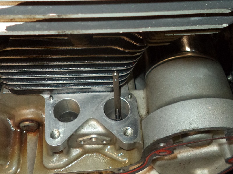
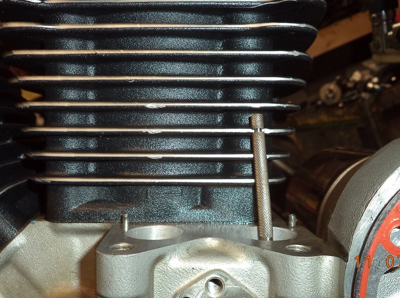
Pushrod lean angle on 91-up engines.
The lifters are square to the lifter bore but they're not quite square to the rocker arm slot for the pushrod.
There is a slight lean angle between the lifters and the rocker arms as shown below.
The pushrod tubes line up square with the lifter blocks and hide the lean angle of the pushrods.
In the pics below, a inside bore gauge is lined up app. straight from the lifter bore to the rocker arm slot for the pushrod.
This is the app. lean angle of the pushrods between the lifter and the rocker arm.
The pushrod angle also changes as the rocker arm moves thru it's arc while the valve is opened and closed. 10)