Table of Contents
This is an old revision of the document!

IH: Engine Mechanicals
Crankcase Ventilation
See also in the REF section of the Sportsterpedia:
Here's a breakdown of XL & K model breathers, set-up, service and upgrades. 1)
52-76 models:
- Timed Rotary Breather
- Design & Function
- Integral with the oil pump, timed to engine rotation.
- 72 & up timing
- Opens 25 degrees ATDC closes 85 degrees ABDC
- 52-71
- Breather timing was less duration.
- Rotary breather connects flywheel area to gearcase.
- Slinger separates oil from air.
- 52-62
- Special slinger on generator.
- Spring loaded bushing in case rubbed end of slinger.
- Breather pipe in gearcase cover open to atmosphere.
- 63-76
- Washer - 1 5/8“ dia. on end of generator.
- 1/16-3/16” Clearance
- Service
- Pump had to be timed, line up these marks;
- Ignition timing mark - center of window.
- Dot on rotary breather should be centered in pump housing notch.
- Changed by repositioning of pump gear to drive gear on pinion shaft.
- 63-76 Slinger washer distance
- 1/16-3/16“
- Increase by grinding generator gear or add generator gaskets.
- Decrease by shimming washer.
- Updates
- 52-71 Breathers
- Install 72-76 pump.
- Changes breather timing - benefit.
- Modify feed supply.
- Plug old fitting in case.
- Run feed to back of new pump.
- One Way Breathers 77-85.
- Design
- 77-78 - PCV type valve.
- Inline with breather pipe.
- 1-5/8” Slinger washer.
- 79-E81
- Stainless reed valve
- Mounted in gearcase cover.
- 1-5/8“ Slinger washer.
- Breather hose to air cleaner '79 & up
- L81-85
- Rubber umbrella valve.
- Very efficient.
- Mounts in gear case cover.
- 1-3/4” Slinger washer.
- All 79-85 breather systems connect to air cleaner.
- Service and troubleshooting
- Inspection:
- All valves should flow one direction only.
- Slinger distance must be 1/16-3/16“.
- Too little - increased crankcase pressures = oil leaks.
- Too much - slinger won't separate oil = oil carry over
- If bike smokes check breather valve operation.
- If it sticks open there will be no crankcase vacuum to help evacuate top end oil
- Updates
- 79-early 81
- Rubber umbrella breather is a retrofit, with 1-3/4” slinger washer.
- Better breathing, less stiff than the metal reed and better sealing - doesn't stay open due to metal fatigue
Breather Valve
The later style system is just like your car. 2)
A deep sump was added to 77> casings and the scavenge side of the oil pump simply pulls the oil from there.
Holes were added between the crankcase and the gearcase / cam chest and crankcase pressure is vented to atmosphere from there.
(much the way your car's crankcase is vented out the top thru the valve covers)
The shallow sump, timed breather system, comes from the aviation world of old.
Piston driven aircraft had to be able to evacuate the oil from the crankcase regardless of engine altitude and that system does that.
At the time Harley adapted that system they were copying the highest engine technology of the day.
They just took too long to abandon it as technology advanced.
The sump system was brought into production to eliminate the need to time a breather to save time on the assembly line.
Documents from HD Racing from the period show no HP gain between the 2 systems when the breather is properly timed ( which didn't happen a lot).
76< Timed Breather Valve
Sub Documents
The rotary breather valve functions to relieve pressure in the crankcase caused by the downstroke of the pistons and it controls the flow of oil in the lubrication system.
It is timed to open on the downstroke of the pistons. 3)
This allows crankcase exhaust air pressure to expel the scavenge oil from the crankcase breather oil trap into the gearcase.
The breather valve then closes on piston upstroke, creating vacuum in the crankcase.
Crankcase exhaust air from the gearcase is sent out the breather tube.
Any oil still in suspension with the air on the way to the breather tube is separated by an oil slinger on the generator drive gear.
A street oil pump has 2 slots and is driven at 1/2 engine speed. 4)
A racing oil pump has 4 slots and is driven at 1/4 engine speed.
All 4 stroke engines takes two revolutions before you come back to the timing marks being all aligned.
How the volume compares when the breather opens as to when it closes: 5)
If we knew that, we'd have a much clearer picture of what actually happens.
This diagram shows the volume swept by piston action in a 1000cc motor.
It shows how much displacement is changed from min volume (0 cubic inches) to max volume(56.2 ci more than min).
 6)
6)
There's only 1.2 cubic inches of net outward flow per revolution.
(ignoring the dynamics of the inertia that the moving column imparts to the actual net movement)
So the actual movement is great but the net change is small.
How much actual movement?
About 45 ci on down stroke and about another 45 on the up for a total of app. 90 ci per rev trying to squeeze thru the open breather.
(which is fully open for exactly 1/2 the time of the 'just open' to 'just close' total time.
90 ci per revolution is about 1-1/2 quarts per revolution.
Multiply that by 5000 rpm and you get 7500 quarts per min.
That's almost 2000 gallons per min trying to get thru the breather.
Obviously that ain't happening and the highly revered 1/4 speed (R) pump has a way smaller opening yet than the street pump.
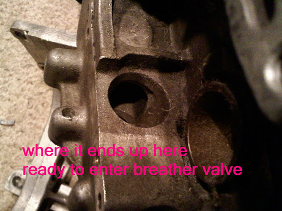
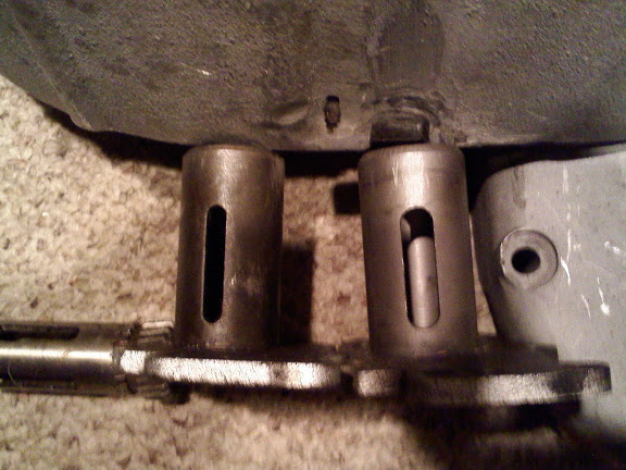
The pics below show the flow from the flywheel cavity to the return pump (applies to 76< only).
In stock configuration, most all used oil ends up in the flywheel cavity.
The small amount that gets supplied to the upper pushrod ball/socket goes into the gearcase.
While the splash oil to the exhaust valves enters the crankcase through the head drains.
There are only 2 areas that get supply (feed) oil pumped to them, the crankpin and the rocker shafts. 7)
 |  |  |
| Left is the unmodified 1/4 speed R valve. Right is the 1000 stock. | R model is the left one. |
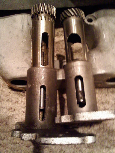 |  |
 |  |  |
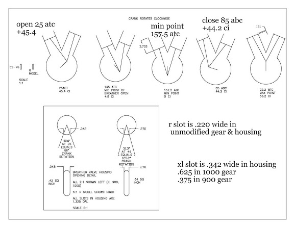
There are only 3 rotor and tower slot widths for all 1937-76 4-cam engines (45, K, KH, XL, UL), which determine the complete breather timing interval. 8)
- Rotor .375“ (88°) + tower .34375” (81°) = 169°:
all non-R 1937-71 engines; the exact opening-closing points vary between engines; 1952-71 K &c. slots are taller than 45 & UL. - Rotor .594“ (146°) + tower .34375” (81°) = 227°: 1972-76 XL; these slots are also taller than 45 & UL.
- Rotor .214“ (99°) + tower .269 (125°) = 224°: all 1954-? KR, KHR, XLR (many mods to this)
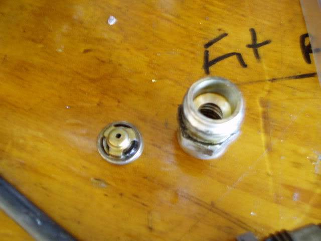
77-78 Breather Valve
WHAT IS IT?
- The complete assembly is part# (24633-77).
- The slang term “FooFoo” comes from the annoying sound that it makes when it gets clogged up with oil residue. 9)
- The engine breather (or crankcase vent) is to allow air out of the lower crankcase, but not in, as the pistons rise and fall. 10)
Without some kind of controlled breather, the lower end would become a 1,000cc air compressor, robbing the engine of several horsepower.
Old time tuners like Jerry Branch, Tom Sifton and Dick O’Brien paid much attention to the engine breather.
They knew it could give them extra horsepower if set up right. - One thing not to do with an engine breather is to simply plumb a hose to the crankcase without some kind of one-way valve or timed breather valve.
It is commonly done, but it wastes power and is not good for your engine.
WHERE IS IT? 11)
- Pre-1977
- There is a timed breather valve built into the oil pump drive, which vents crankcase pressure into the cam timing chest.
A six-inch metal tube hanging down from the timing cover near the generator drive, at the 6 o’clock position vents that controlled pressure to atmosphere.
A metal disc on the end of the generator drive gear centrifugally separates oil from the air as it is discharged overboard.
-
- The timed breather on the oil pump drive was dropped.
A new design breather valve (24633-77) was used in late 1977 model XL/XLCH/XLT engines produced around October 15, 1976.
All 1000cc engine numbers (3A, 4A or 2G) 27940H7 and above had the new breather valve.
It serves the same function as the gear driven breather valve used on 1976 and earlier engines to maintain a partial vacuum in the engine and prevent oil leakage.
Due to it's improvements in doing so, it was suggested to be retrofitted to all 1977 XL & XLCH engines. - The one-way valve is contained in a fitting which screws into the gear-case cover below the generator mounting boss.
The existing breather outlet pipe screws into the bottom of the new fitting.
The outlet pipe, because of its lower position, must be directed outside (instead of inside) the frame tube.
The rubber hose at the pipe outlet must no longer be used. - Because of the higher vacuum existing in the engines equipped with this new breather valve, a higher pressure oil pump check valve (26435-76A) was installed in L1977 oil pumps at the same time to provide higher oil pressure at the oil pressure light switch.
- The new valve opens at 4-6 PSI whereas the old valve opens at 2-4 PSI.
Pumps having the new valve are identified with a green dot.
The existing 0-ring (26433- 77) was used for both new and old valves. - An external non-return valve was plumbed into the vent tube sticking down from the timing cover at the generator drive.
This allows air out, but not in. It is sometimes referred to as the foo-foo valve.
Searching the XLFORUM for foo foo valve or foo-foo will lead to extensive discussions of this mystical device.
| 77-78 Crankcase Ventilation Valve 14) | ||
 | 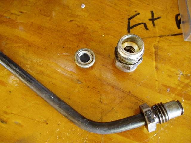 |  |
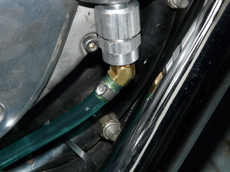
- This vent line mod was done due to problems fitting the stock tube as it hit the exhaust pipes.
- Thread size for the breather fitting is 5/8”-11.
- A piece of aluminum threaded rod, cut a small length to thread into the breather and drill / tap the hole for an 1/8“ pipe thread.
- A 45 ° hose barb fitting was installed to connect a length of hose that leads back along the frame.
This way the oil mist gets directed out back and doesn't collect along the frame and engine.
| Stock tube removed, fitted with 1/8” 45 deg barb fitting. 15) | |
 |  |
1979-E1982
- The external foo-foo valve and the six-inch metal vent tube at the front of the timing cover were done away with.
Instead, a one-way foo-foo valve was built inside the timing cover (26909-79A), (26909-82).
A rubber breather hose then ran from the generator drive area of the timing cover, at the 9 o’clock position.
It connected to the stock air filter so that any oil mist was fed back through the engine, making the EPA pollutocrats more happier.
(than they were with the idea of engine oil spraying out into the atmosphere)
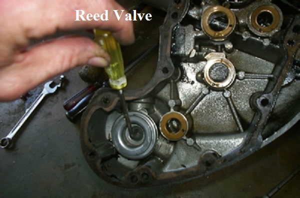
The generator had a (1-5/8“ O.D.) oil separator washer on the end of the armature shaft. 16) - The breather valve is a simple reed valve with a flap made of spring steel over a hole.
Unless it's visibly damaged, there's no reason to mess with it. 17)
If it stops up, you can try and spray some WD-40 in the hole to clear it.
Here is a pic of IronMick's internal foo-foo in his post-79 model on the left.
You can see the 9 oclock fitting and the 6 oclock fitting both enter the same cavity.
The oil slinger is the big fat washer on the end of the generator in the (R) pic below.
 18)
18)  19)
19)
L1982-1985
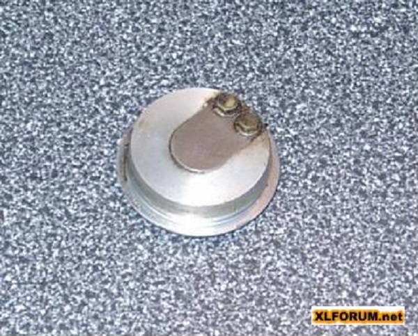
- The internal crankcase breather valve was redesigned to incorporate a rubber umbrella valve attached to the base plate along with a larger diameter (1-3/4” O.D.) oil separator washer on the generator armature. 22)
Many of these bikes with custom air filters simply run that hose down to the bottom of the frame and let the oil mist blow out in the time honored manner.
That is fine too, as long as you are not an EPA man.
The pic on the left shows the breather line coming out at the 10 o'clock position going up to the air cleaner.
The pic on the right is of an 85 cam cover with the foofoo valve (baffle tube) off to the left of it.


Both the 10 o'clock and 6 o'clock outlets come out of the same chamber that's controlled by the internal one-way crankcase valve. 25)
When both are opened, the crankcase pressure can evacuate more quickly / completely.
Opening the 6 o'clock hole doesn't bypass the factory crankcase venting arrangement.
A small amount of oil occasionally drips from it.
But that's better than having it accumulate in the air filter and blowing all over the right side of the bike.
Plus, the extra vent seems to let the motor wind up a little more freely.
No filter is needed when plumbing to the 6 o'clock breather line. 26)
They just collect oil and drip.
You can use an old inline glass gas filter (remove the filter itself), hooked the vent hose to it, and zip-tie it under the frame.
It'll be horizontal to the bike and will collect the oil so it won't drip all over .
And it'll vent freely with no filter or other obstructions.

Breather Valve Alternatives
See also Converting Head Breathers to Cam Chest Breather in the REF section of the Sportsterpedia.
That mod is for Evos but the information on the Krankvent is there.
- There is a product called a Krankvent that can be plumbed into the lower, 6 o’clock position as an alternative to a stock foo-foo valve. But they are not cheap.
- Automotive PCV valves are not really made to handle the revs or air volumes of a Harley. While a car engine is bigger, it has one piston coming down while one goes up, so not much change in internal crankcase volume, so not much breathing to be done. A Harley has two pistons and rods on one crankpin, so is one giant air compressor.
- Some guys have found that plumbing in a 77-78 foo-foo valve on the later model engines improves breathing.
LINKS- Discussion on foo-foo valves and engine breathers pics etc here: http://xlforum.net/forums/showthread.php?t=213630
There are other threads but this pretty much covers it all anyhow. Pretty simple but seems to cause repeated headaches for such a pesky little thing. 28)
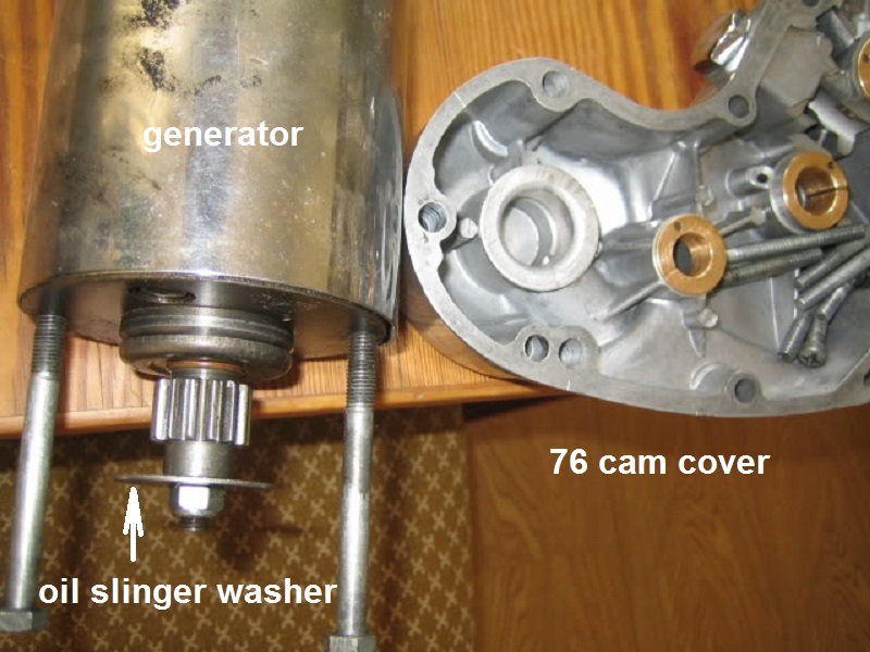
Oil Slinger
Crankcase exhaust air escapes from the gearcase through the external breather tube. 29)
Any oil carried still carried by exhaust air is separated from the air by an oil slinger on the generator drive gear.
The oil slinger is powered by the generator and deflects oil away from air leaving the breather outlet to atmosphere.
It spins oil away from the breather hole by centrifugal force and separates the oil mist in suspension with the exhausting air.
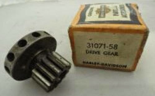
There are two different gears. 30) 31)
The first, from 58 to 62, has an integral slinger. They look like a gear with a tinker toy connector glued on the end.
It's a lathe machined affair combined with a spring loaded sleeve in the cover.
These are great gears but no one repops them. They are expensive and hard to find.
In late 62, they went to a more standard looking gear used with the big washer style slinger. Not as good but a lot cheaper to make.
Just get rid of the timing cover sliding bush/spring if you want to use the big washer instead. 32)
The sliding bushing assembly makes the early slinger works as a “labyrinth” since the air has to travel through its center to get out.
That's why it's a better set up than the simpler washer setup. It doesn't allow for any oil to escape except if your engine is totally wetsumped.
But the early slinger will work without the sliding bushing, just not as good.
And you can't use the sliding bushing with the washer setup.
From Dr Dick on the slinger and oil loss: 33)
52-62 used the old 'daisy wheel' gear that physically sealed to a spring loaded top hat in the cover.
These had great oil control but are pretty restrictive to air flow. Bad air flow can rob hi RPM horsepower.
Race bikes used big breather passages, fittings, hoses and pass lots more oil.
Bikes 52-76 work different than 77>.
77> don't have as much oil flying around in cam chest and the 77-78 one way foo foo keeps air flow volume to atmosphere low.
These bikes tend to drip from the tube after a ride. Oil gets trapped in the nook and crannys of the foo foo, then leaks out.
76< is a totally different dynamic.
The crankcase volume under pistons is much smaller than 77> and air flow to the cam chest is much more restricted.
The 77> cam chest can act as a air reservoir for crankcase volume and the foo keeps the amount air in the cases low.
Less air equals less pumping losses. Used oil gets picked up in the crankcase itself (not in the camchest).
So the slinger has an easier task in 77>.Not so for 76<.
Oil collecting in the crankcase needs to be blown into the camchest to be picked up by the return pump.
High air flow from the crankcase thru the timed breather to the camchest evacuates the crankcase oil good.
That same high flow 'opens' the crankcase volume to the camchest.
Opening the camchest vent size to atmosphere adds another level of free breathing. All this is good for power.
As you allow free air flow thru the motor, you also allow free oil flow too. So far, so good, right?
The down side: As air flows in and out of the camchest vent (puke tube), so does the well suspended oil.
Race bikes can pass a lot of oil to atmosphere way more than acceptable for a street ride.
So to separate oil from air, a slinger is used. It functions by forcing air thru a small passage that has a spinning disc.
The disc sets up centripetal force in air passing thru passage.
The smaller the passage, the better the oil control and the smaller amount of air that can freely pass. Bad for power-good for oil control.
Reducing the slinger clearance (to a degree) is like putting mufflers on a race bike.
The MoCo is more interested in happy customers than the efficiency of a single sub-system.
Everyone seems concerned about oil loss. Not a word about the other side of the coin - the cost in performance of good oil control.
The factory knew their customers wants and it will cater to that market. Good business sense.
In the boardroom, the question was:
How do we free up more power while keeping oil loss at a level that the customers are accustomed to?
From past experience, they knew that oil evacuation was more important than air evacuation.
And they learned that keeping air speed in the camchest low allowed oil in the cam chest to 'rain down' to the return pump.
(instead of staying in suspension and relying on a restrictive slinger to keep flow thru puke tube and to the underside of bike acceptable.
So if they could concentrate the crankcase oil in a trap, then blow that oil into the camchest with a small amount of air;
They get the most power with the least chance of oil loss.
A look at the shape of the transfer passage between the crankcase and the breather valve shows the result of that line of thinking.
So in mid 62, they reduced oil pump capacity but increased the return to feed ratio. Less oil in means less oil to move and less drag.
More return over pump helped more yet.
The small pump dried the camchest well enough that the slinger could be opened up = more air flow.
Good-bye power robbing daisy wheel - hello fender washer.
The 62-71 oil pump has a smaller feed side than the 61<. Compared to the 61<, the return is bigger in the -62 pump. Less feed, more return. 34)
The 72 pump feeds and returns more than any of the previous.
The washer itself looks to be just a normal fender washer.
You may find an in use washer with grooves stamped in it. Grooves are an old mod done by owners/wrenches (not the factory)
It is large enough in diameter to make installing the generator tricky at times.
5/16“ fender washers come in 3 sizes. 1.375” (common), 1.500“ (hard to find), 1.625” (real hard to find).
OEM is 1.625“ although the 1.500” washer usually works fine. The 1.375“ washer may pass more oil out the vent than the bigger ones.
Factory fitment of generator gear washers: 35)
- 1957 used the model 52 generator, no nut or washer.
- 1958-1962 used the daisy wheel gear. Uses washer (6324) - (.312” x .688“ x .094”)
- 1963-1978? later used just the -63 slinger. All iron bearing housing generators were like this.
- 1979-81? used -63 slinger and pn (6372b) - (.312“ x .750” x .062“). The double washers were used on the gens with the alum bearing housings.
To inspect or replace the slinger washer, remove the two bolts from the cam cover that hold the generator. 36)
Remove the wires from the generator and with a little fiddeling around, the generator will come out. The washer is on the end of the armature.
Make sure to put a new grade 8 nylock nut on if you remove the old one. They should only be used once or they lose their grip in that hot, oily environment. 37)
Check the oil separator bushing to bore fit in the cover. It should be a light press fit.
If it is loose, you can probably remove it, clean up the boss with brake cleaner and reinstall the bushing with Loctite or epoxy. 38)