Table of Contents
This is an old revision of the document!

IH: Oiling & Lubrication - Sub-03P
77-85 Oil Pump Inspection and Diagnostics
Diagnosing Problems with the Oil Pump
Below are some general wear issues as well as secondary issues that may affect the operation of the oil pump.
General wear is a given as all moving parts will eventually show an amount of wear.
Secondary damage or problems are sometimes not thought of and consist of other parts of or in the motor that may end up damaging the oil pump.
Note: Any time there is a question about the oiling system, FIRST MAKE SURE THERE IS OIL RETURNING TO THE OIL TANK.
- Possible causes of low oil pressure from the oil pump:
- Cracked gerotors or too much clearance between the inner and outer gerotors will lower outlet pressure / oil flow to the motor.
The gerotors work by picking up oil from the inlet cavity and moving that oil to the outlet cavity.
As the gerotors turn, previous oil deposited in the outlet cavity is pressured to keep moving the next time the outlet cavity is filled on rotation.
If there is a crack in a gerotor or a wide clearance between inner and outer gerotors, pressure will be forced into these areas instead.
Basically you lose some pressure on the outlet side as some oil is simply being transferred from the outlet side back to the inlet side of the pump. - An out of round gerotor bore in the housing or cover can reduce oil pressure.
This equates to too large of clearance around the gerotor OD lessening the hydraulic seal.
This can be caused by the separator plates and/or gerotors getting sideways in their bores and wearing the surrounding aluminum. - Air leakage into the pump can result in low oil pressure.
If oil can leak out, air can leak in. Just as the oil return in the tank can be seen in spurts, the feed side also comes in spurts.
So there is a small instance of high and low pressure coming from the feed gerotors to outlet pressure.
This can equate to a push / pull situation inside the oil pump (both having their own pressure cycles).
So the pump can leak oil out of cracks and a quick cycle of vacuum (or reverse pressure) can pull in air from the outside into the pump.- Loose hose clamps at the oil pump and/or oil tank feed hose fittings or split hoses can create air leaks.
If using crimped hose connectors, check them to make sure they are tight. If using worm drive hose clamps, make sure they are tight.
Also make sure they haven't been tightened too much (which can cut into the hose under the clamp).
This will prevent air leakage into the system which could cause loss of oil pressure due to an airlock in the oil pump.
Also periodically check all hoses for rot. - Cracks in the pump cover (big or small) at the area of the oil pressure switch are also a source for air intake.
When installing the oil pressure switch, make sure you don't tighten it too much.
5-7 ft/lb (or hand tight plus a nudge) is all it takes to tighten the pressure switch.
Much more than that will simply crack the aluminum around the threads.
Click Here to read more about the oil pressure switch in the Sportsterpedia. - The oil pump has to be primed or it will not pump oil.
If you've recently removed the oil pump or feed hose (drained the oil from), air will be present instead.
It takes a hydraulic seal around the gerotors to create oil flow/pressure.
There have been several reports of work done on the oil pump or an oil pump swap in where no oil flow was noticed during the first ride afterward.
Any time the oiling system is worked on, make sure to first check that there is return oil coming back into the oil tank.
(especially before risking a no oiling condition on the road)
Once the oil pump is initially primed, it should stay primed until such time the pump or feed hose is later removed.
- General Wear / Damage Issues: (things to keep in the back of your head when dealing with oiling issues)
- Gerotors can crack but still work to a point.
That point may be where it finally wears out the pump housing to gerotor OD clearance thus delivering less oil to the motor.
There is no spec for gerotor to housing clearance.
But even hairline cracks in a gerotor will allow it to expand when hot.
This will eat away at the housing bore, heat up the pump and internals causing damage to other pump parts as well.
Cracked gerotors will also produce less oil pressure. - Gearshaft pins can shear off, stopping either the feed side or return side or even both from turning.
The solid pins in the side of the gearshaft are responsible for turning the gerotors.
The pins will wear and sometimes they will shear off. Each gerotor set has it's own pin.
So it's possible for the pin on the return side to shear with the pin on the feed side staying in tact or vice-versa.
So you could have feed oil to the motor but no oil return to the tank or vice-versa.
Always check for oil returning to the tank when diagnosing any suspected oiling issues (or any time after checking the oil for that matter).
Never check oil level without the motor being up to operating temp.
So before you shut the motor down to check the oil, have a look in the tank to verify that oil is returning. - The roll pin in the oil pump housing can shear or pull out.
This may be due to foreign matter in the feed or return cavities.
The feed gerotors are already under pressure due to the spring washer design alone.
Any foreign objects that enter the pump can increase the pressure against the outer plate.
From the return side, it can push the inner plate toward the feed side. From the feed side, it'll create more pressure on the feed side only.
If the extra pressure is enough to grab and spin the plate hard enough, that could be enough to knock the pin out of it's hole in the housing.
If the roll pin comes out, it will cause damage to the oil pump.
If it gets lodged between the inner and outer gerotors, it'll most likely crack the outer piece (weaker of the two pieces).
If it gets under the feed gerotors, it'll get dragged across the gerotor surface in the cover.
This will end up in scratches on the machined surface and lower oil pressure from the pump due to the scratches.
With the roll pin out, the outer plate under pressure can spin and wallow out the feed bore in the housing around the plate.
Oil Pump Inspection
With the replacement of the gear driven oil pump by the new gerotor style pump;
HD issued a recommendation to dealers regarding servicing of the new style oil pumps. 1)
Zero gerotor (gear) side clearance must be maintained by the flat spring between the upper and lower separator plates for adequate oil pressure.
For the spring to function properly, the upper face of the lower feed gerotors must extend slightly above the cover to prevent any side clearance.
(which would allow oil to get past the gerotors and reduce oil pressure)
If you have reduced oil, no oil pressure (oil light comes on or stays on) or otherwise need to disassemble the oil pump for any reason,
The gerotors and their corresponding operating surface in the housing and the cover should be checked and serviced accordingly.
Inspect the oil pump cover and body
Inspect the ridge in the cover
- Using a straightedge across the feed gerotor set (installed) surface;
Measurement should be taken with a feeler gauge from the gerotor surface to the ridge of the edge of the aluminum cover.
The thin, feed gerotors (26492-75) in the oil pump cover (26486-75) should extend .001“-.005” above the cover's aluminum ridge.
The later feed gerotors extend up to .011“ above the ridge.
If the feed gerotors do not extend above the ridge within the specified range,
Remove and sand the ridge evenly until the gerotors extend properly when inserted.
Lay some sandpaper on a flat surface (#280 grit then #400 grit to finish).
Invert the cover and sand the ridge then check the measurement with a micrometer.
Make sure that both the inner and outer gerotors are the same thickness also.
Inspect the gerotor surface for flatness in the oil pump cover and housing
An oil pump cover found with an uneven gerotor surface should be removed.
If the gerotor widths measure equally but they are not equal in height when placed into the cover, the cover surface is not flat.
If the gerotors will not sit flat in the cover then the cover should be replaced.
Be sure to check the gerotors in the new/replacement cover using a straight edge to assure a level surface and the proper elevation above the ridge.
Be sure to check the gerotor surface in the housing also.
Inspect the gerotor surface in the cover and housing for deep scratches or gouges
Many (most perhaps) used oil pumps have scratches on both the gerotors and pump surfaces that the gerotors ride on.
But, there is one certain spot that seems to be scratched more times than others. 3)
It's on the larger of the two pads in the pump body and the cover seem to usually have more wear.
Sometimes, the small pad is scratched or damaged also but not always.
The gap between the inner and outer gerotors on both the feed and return sides tends to be scratched as in the pics below.
Debris caught between these two gears cannot slide over and fall to the other cavity and out of the pump.
It gets locked between the teeth and ripped across the aluminum surface.
In theory, no particles of any size should be able to spin around to the small pad.
This is mainly due to the pressure generated by the spring washer and the gerotor spacing there.
Also, any debris picked up from the source side cavity should drop down into the feed side cavity and out of the pump.
The side toward the motor is where oil is transferred to and from the pump.
The inner and outer gerotors come together on the other side (right side).
This spacing relationship doesn't change between the motor side or the outside of the pump due to the offset gearshaft.
But in reality, debris gets caught in or between the gears and gets dragged over the aluminum flats.
Some then find their way under the gerotors while the spring washer flexes from the stress.
The debris spins around under the gerotors and wears scratches in the flats (pads) or worse.
There should be some amount of reduced pressure because of the scratches (depending on how may and how deep).
Pressure generated to the output cavity can squirt back to the input side through these scratches.
How much pressure loss would depend on the width, depth, length of the scratches and oil viscosity at the time.
To make the pump inoperative or not make pressure (from the scratches alone);
The scratches would have to be proportional to the relative volume of all four gerotor reservoirs combined.
Then, the check valve would have to accept less pressure flow than the backpressure from the pump.
The gerotor surface in the cover would have to be eat up pretty bad to make the pump completely ineffective.
The pump would have less pressure loss with multi-weight or straight weight oil when cold than hot.
They'll both flow faster when hot.
| Gerotor rotation (cover shown) 4) | |
 |  |


The pump body below had an aluminum chunk come into the return side and just sit there on top of the spinning return gerotors.
That lessens the amount of return oil the pump can have in the return cavity at once.
The chunk also got knocked around with chips breaking off of it.
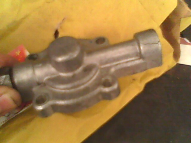
| Oil pump from 1983 model 5) |
 |
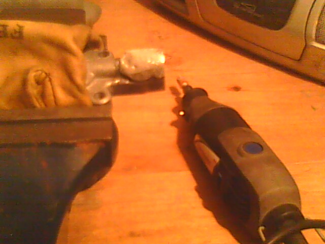
Check for cracks in the housing and cover
The cover below was cracked at the oil pressure switch end from tightening the pressure switch too tight.
The crack was welded over and a Dremil tool was used to reshape the cover.
Due to warpage during welding, the threads need to be chased with a tap to straighten them back out.

Inspect the gearshaft and bushings for damage or wear
- Check the gear teeth for pits, breakage or wear. Replace the gearshaft as necessary.
- Clean areas where the shaft sits in a bushing with steel wool if needed.
If it's not possible to smooth the areas out, replace the shaft. - Inspect the gearshaft bushings both the housing and the cover.
Look for scoring, excess wear and noticeable damage. Replace as necessary. - Measure the gearshaft to bushing clearance on both the upper and lower bushings (maximum .0005”).
Replace any bushing with a clearance larger than that.- Clean the bushings and gearshaft of all oil / residue before measuring.
- Use a telescoping bore gauge to find the bushing ID.
Do not use a caliper alone to measure the ID of the bushings as it will not be accurate. - Measure the bore gauge (caliper shown below).
If you're not comfortable with using a caliper, then use a micrometer. - Measure the area on the gearshaft where each bushing will reside (upper portion for upper bushing, lower portion for lower bushing).
- Subtract the gearshaft OD from the bushing ID and that's the clearance referenced in the FSM.
Pics 8)
![]()
![]()
![]()
Inspect both gerotor sets
Clean both gerotor sets with solvent, brake cleaner et., and inspect them closely for cracks.
It may be hard to see cracks from a distance or when the gerotors are oily / dirty.
The outer return piece below was cracked but not all the way through.
Being cracked at all is still a problem (could result in lower oil pressure).
Replace any gerotors with damaged teeth, nicks or cracks. The problem will only get worse.
 9)
9)
Check inner to outer gerotor clearance on each gerotor set**.
Each gerotor set is made with an inner and outer piece. Mesh the two pieces together (as they normally would sit in operation).
- Arrange so there is 1 inner tooth facing the center of the wide outer radius.
Use a feeler gauge between the inner tooth and outer radius there for a maximum of .004“ clearance between them.
If the clearance is larger than .004”, replace the affected gearotor set. Repeat for the other gerotor set.
- Measure the height of each inner and outer gerotor set.
Each inner and outer piece (feed side) should be the same height, each inner and outer (return side) should be the same height.
Replace gerotors as a set respectively if the inner and outer pieces are not the same height.
A micrometer will reveal tighter measurements rather than the caliper used below.
However, there are so many small variances in these pumps that less than .001“ increments isn't going to be the hill to trash your pump on.


Inspect the seals and O-rings
- Inspect the check valve and cover to housing O-rings and make sure they are not damaged/deformed/out of round and seal tightly when in place.
- Inspect the gearshaft seal for deformity and / or wear.
Inspect the check valve
- Make sure it's not clogged and the internal spring closes the cup / disc properly.
The spring loaded cup inside the valve should be free to move and should return to it's closed, seated position.
It the check valve is damaged in any way, the complete valve assembly should be replaced.
There are no replaceable parts to it.


Inspect the spring washer
- The spring resides between the separator plates (between the feed and scavenge gerotors).
Replace the spring if there are any “fingers” broken.