Table of Contents
This is an old revision of the document!

REF: Primary Drive & Clutch
Broken Rotor / Clutch Basket Magnets
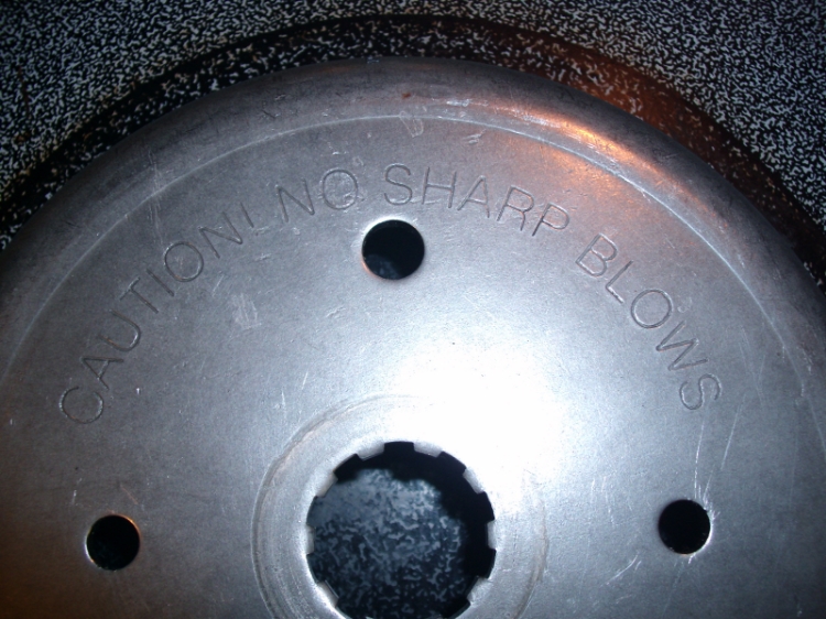
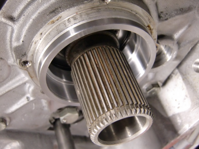
If you look on the clutch of your late Ironhead/ early EVO you'll see a warning. It says “Caution No Sharp Blows”. The BT rotor I obtained says the same thing. 1)
| This is what can happen when you use a hammer on the clutch basket / engine sprocket rotor (respectively to your year model) 2) | |
 | 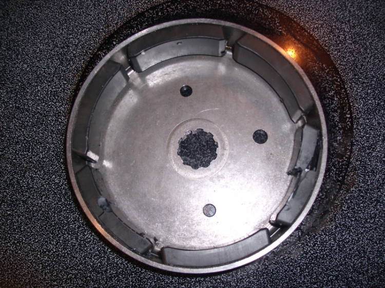 |
This was done on purpose as an illustration. “I started slow and then went a little harder until I heard a couple of the magnets drop out”. 3)
The Dreaded Clutch Basket Wobble
"The Harton Fix" (Late 84-90 Rotor / Clutch Shell Magnets)
Or, “How to fix the dreaded clutch wobble” 4) 5)
This is a fix for the famous clutch shell wobble breaking magnets & stator issues on the late 84-85 ironhead and 86-90 evo engines without going to aftermarket products. The V-twin clutch and the zippers trapdoor are nice parts but I don´t think that is where the problem started. The wobble on the clutch gear splines is what I think is the biggest problem to fix in most cases. If the clutch shell can´t wobble, the magnets will not hit the stator and the problem is fixed.
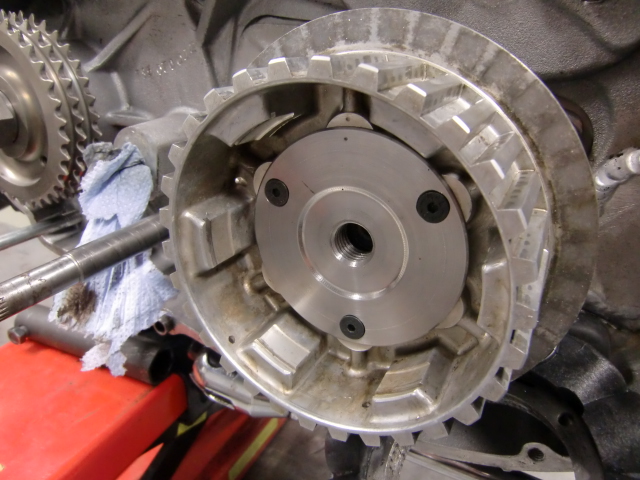
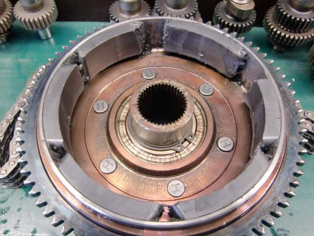
Repairing the hub magnets
- With a used clutch housing with good magnets, take all the magnets out first and re-glue them with epoxy (Loctite 3455 used in the pics below).
- Here is a template you can make to evenly space the magnets when re-installing them
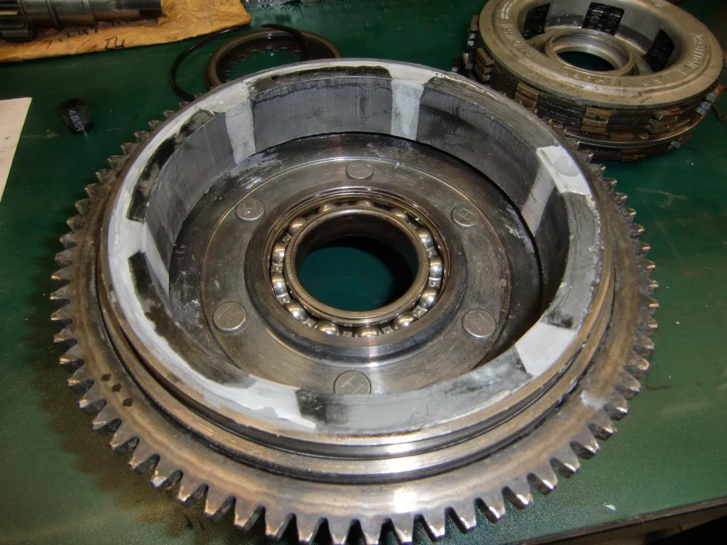
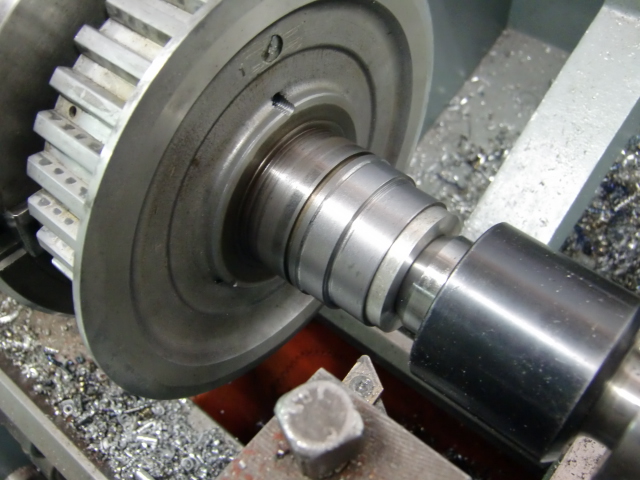
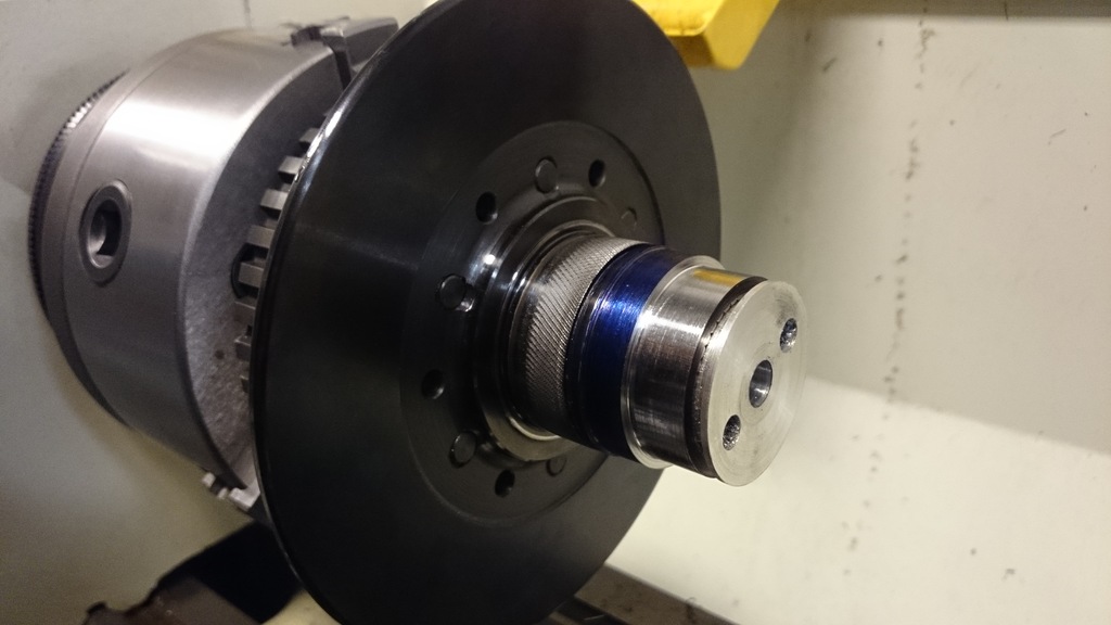
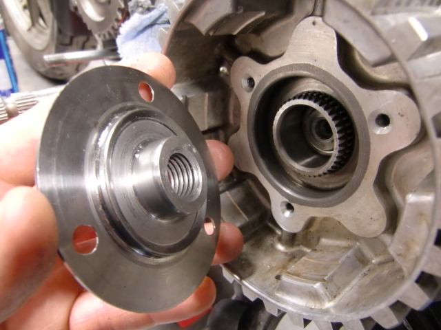
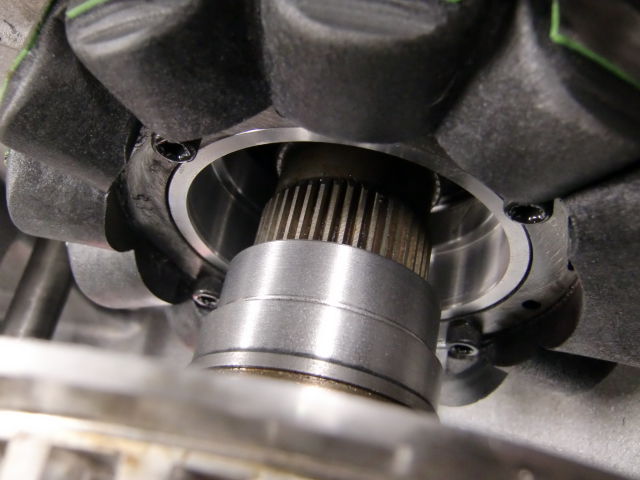
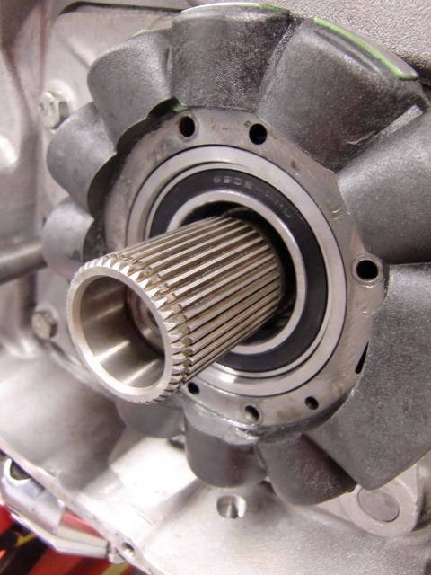
Mount an extra bearing at the back of the clutch
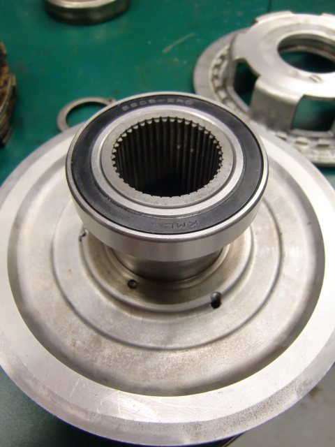
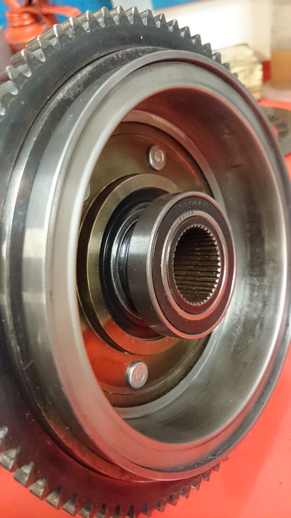
The bearing used in this example is a 6908-2RS ( 40 x 62 x 12mm ) to support the hub and fixed to the gear at the front of the clutch.
This way the clutch will not wobble on the splines.
- You'll need to fabricate a sleeve to hold the bearing.

Calculating the sleeve
These dims are for reference comparison only. 10)
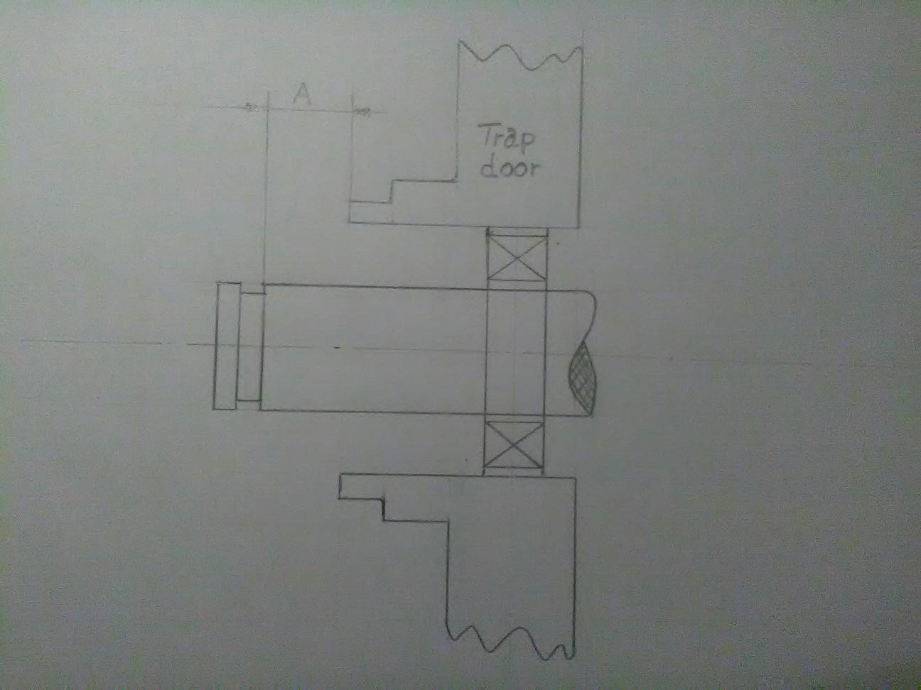
- Find distance A from the groove for the lock-ring to the start of the hole in the trap-door.
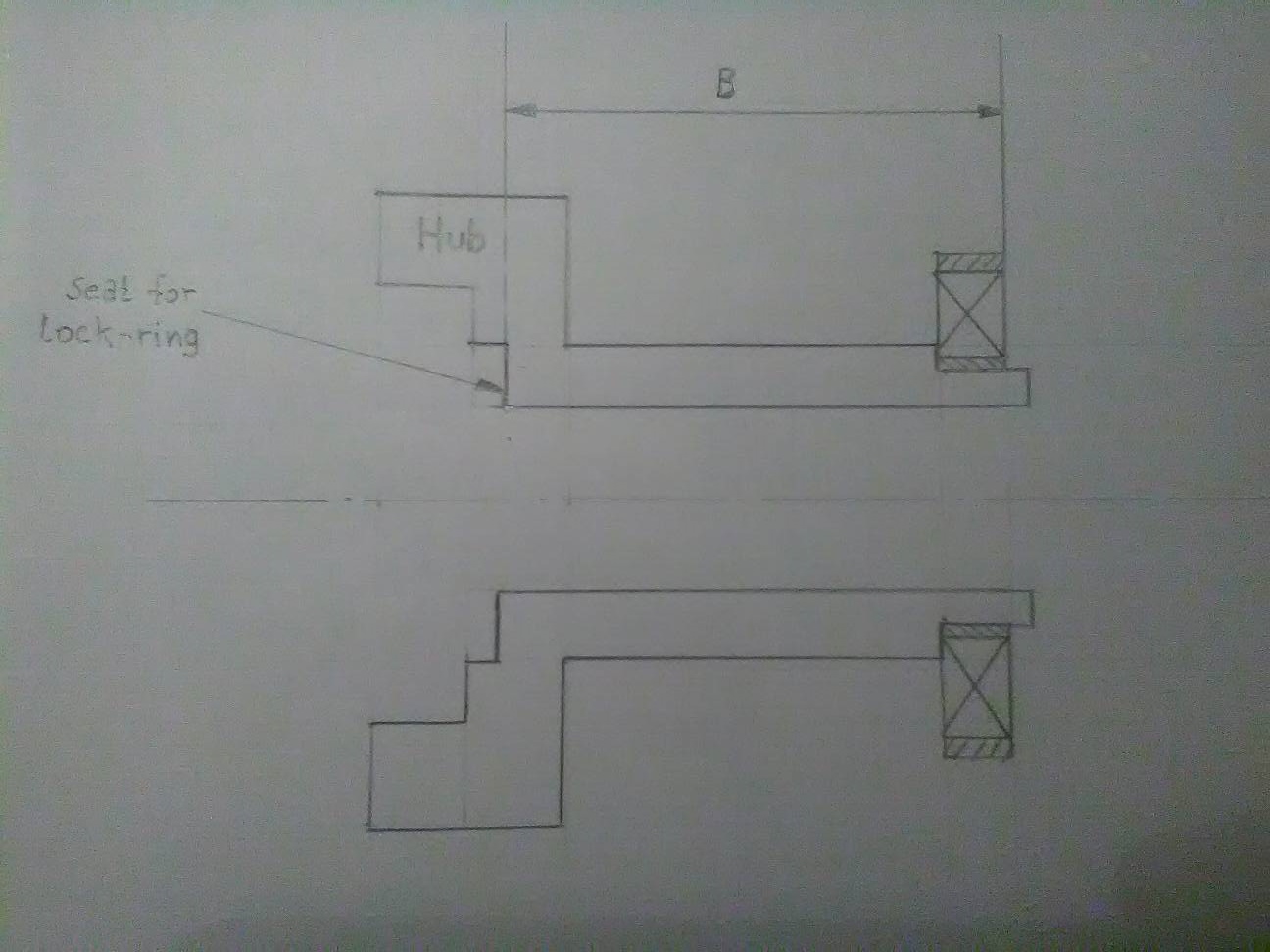
- Find distance B from the seat for the lock-ring in the hub to the far side of the bearing.
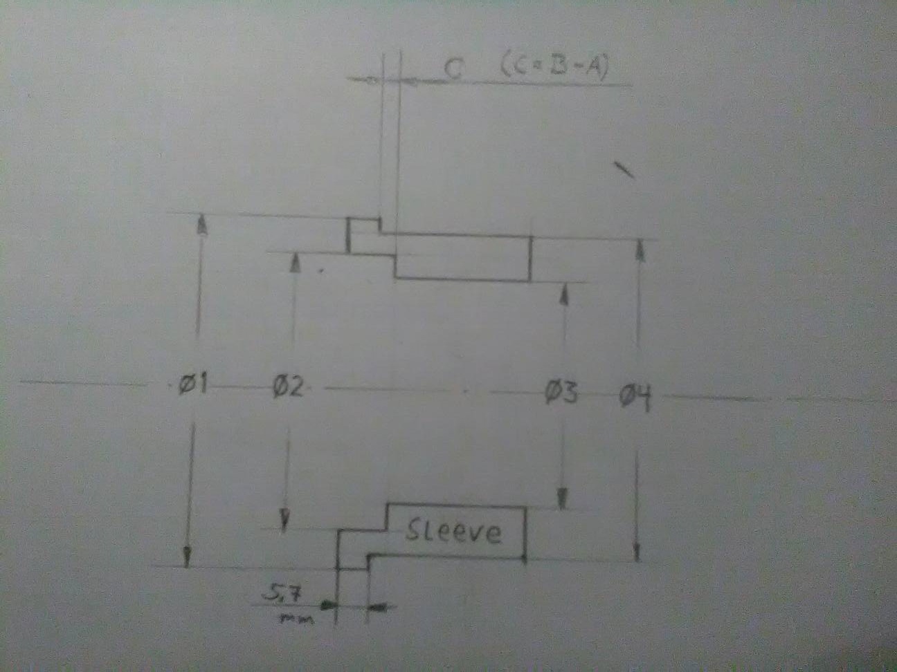
- Then, distance C = (B + the thickness of the washer under the circlip) - A
- In the image below, the bearing is drawn a little inwards from the end of the hub just to make a point it is the bearing that matters.
However one should try to make it flush with the end. - The distance 5.7mm is to make the sleeves outer protrusion flush with the stator. It can be made longer if needed.
- Ø1 = 70.6 mm (2.780“)
- Ø2 = 62.0 mm make slight press fit for bearing 6908
- Ø3 = 58 mm
- Ø4 = 63.5 mm (2.5”) make it to press fit into the trap-door.
 |  |  |
| App. dims for the bearing race (however, you must do the measuring for Your application). These were taken for an aftermarket hub. These are the updated pics by norseXL 11) |
||