Table of Contents
This is an old revision of the document!

EVO: Engine Mechanicals - Sub-04A
Removing the Rocker Boxes
See also Rocker Box / Rocker Arm Inspection and Repair in the Sportsterpedia.
First, it is suggested to acquire a Factory Service Manual (FSM) before doing any work on your bike. 1)
Installing or removing the rocker boxes is not complicated. 2)
But, it could very easily be done the wrong way with bad results.
While it is mostly just unbolting parts and bolting them back on, some care should be taken.
Simply unbolting things and throwing them back together can cause harm to engine parts.
Plan Ahead
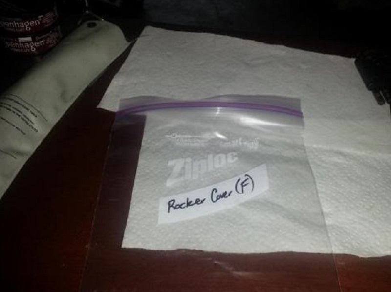
Plan ahead to have a place to store bolts and parts.
This way they won't get mixed up or lost and it'll make reassembly go smoother.
You can use a Ziplock bag or an old piece of cardboard for each set of rocker bolts and parts.
 3)
3)  4)
4)
Before Removing Lower Cover
Make Room to Work
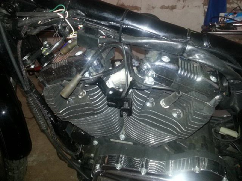
Disconnect and remove the fuel tank.
The tank will be cumbersome to work around if possible.
Remove any other items between the framand the rocher box that may hinder removal, plug wires, etc.
The rest can be left on unless you just want or need to remove them anyway.
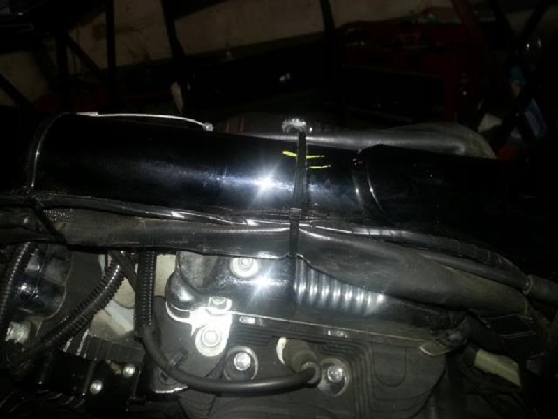
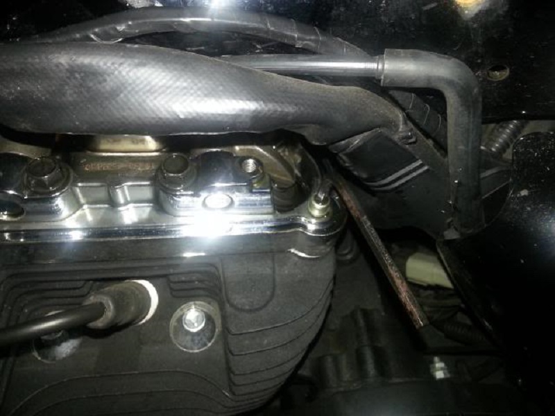
You may also want to cut and remove the wire strap on the main harness over the rear cylinder.
Then you can nudge the harness out of the way for removal of the top left rocker bolts.
| Fuel tank and other appurtenances removed. 5) | |
 |  |
Bolt Removal Sequence
The FSM is quite clear in the proper order to remove the bolts. 6)
Removing them in the proper order also prevents potentially warpage of the cover(s).
It also mentions making sure that both valves are closed prior to removal.
On assembly, it's even more important to slowly tighten things in the proper order to allow the lifters to bleed down.
(prevents things like bent push rods and destroying the cam bushings).
Also, make sure you can spin the push rods BEFORE turning the motor over the first time.
Obviously, you can skip these steps and get lucky.
But, why? Just follow the manual, it's easy enough to do correctly.
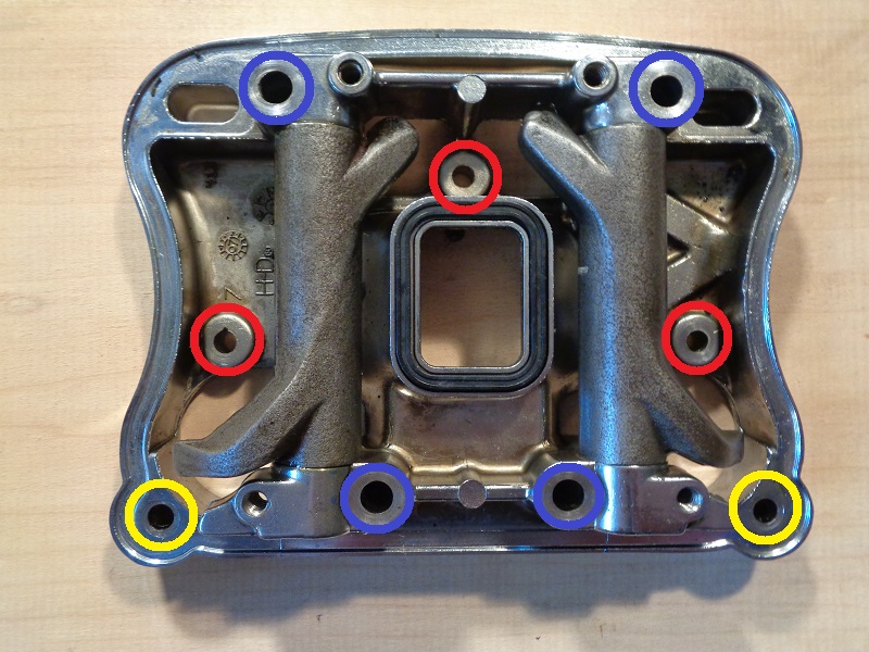
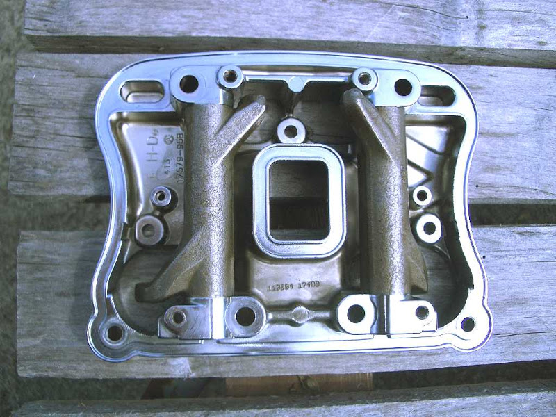
Below is a picture of the lower rocker box (with no hardware),
The circled areas are where the bolts would be:
On disassembly: 7)
- The yellow bolts would be removed first, then the red, and then slowly and incrementally loosen the ones in blue.
(the FSM suggests 1/4-1/2 turns at a time to relieve spring pressure evenly) - An easy way to remember the order is to work on the smaller bolts first and then the larger ones.
On assembly: 8)
- Work in the opposite order. Blue→red→yellow.
It is suggested to do this slowly (one turn at a time) and for the blue ones to do it in a cross pattern.
This is to bleed the lifters properly. - An easy way to remember the order is to work from the larger bolts to the smaller ones.
Torque values:
Installing the bolts in the correct order doesn't take much longer and saves some potential headaches.
While many experienced guys won't use a torque wrench on the smaller fasteners, it is suggested to use one.
It doesn't take much to strip one of these for new or experienced mechanics.
- Blue - 18-22 ft-lbs
- Red - 135-155 in-lbs
- Yellow - 135-155 in-lbs

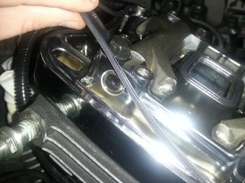
Remove the 4 screws with captive washer and fiber seals on the top section.
The FSM says to discard the fiber seals and replace them with new ones. 11)
That'd be an individual judgment call depending on condition of the old ones.
However, they are cheap enough to have some on hand as spares when needed.
If installing new seals, the old ones can be stored for spares if needed.
| These two screws are more difficult to get to with the wiring harness attached to the frame. 12) | Put the screws and washers safely away. 13) |
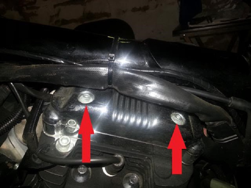 |  |
86-03 engines have rockers boxes a three piece rocker box.
The outer cover (aka upper cover).
The spacer (aka middle cover).
And the inner cover (aka lower cover).
2004 and up rockers boxes only have two pieces.
The outer cover (aka upper cover).
And the inner cover (aka lower cover).
 14)
14)
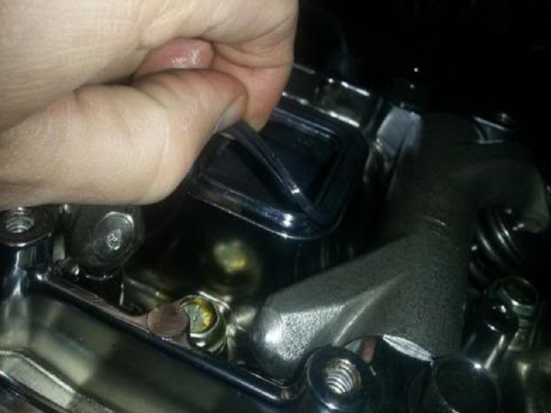
Remove the outer cover.
You may have to nudge it a bit with a rubber mallet to break it loose to lift it.
Then remove the crankcase breather.


The FSM says to remove and discard the gaskets. 19)
Unless they are in bad condition (pinched, torn etc.), they can be reused.
Again, this is a judgment call.
These gaskets can be easily replaced if you have a leak from re-using the old ones.
If installing new gaskets, the old ones can be stored for spares if needed.
 |  |
Rotate the engine until the both valves are closed on the cylinder you're working on.
This can be done by shifting the transmission in 5th gear and rotating the rear tire forward (with the bike on a lift).
It isn't necessary to bring the engine to TDC (compression) but that would accomplish the same thing.
Both valves need to be closed to relieve the pressure from the lifters to the rocker arms (thru the pushrods).
See more about Finding TDC (compression) using the rocker arms as a visual in the REF section of the Sportsterpedia.
Before removing the screws, walk away for 20-30 minutes to allow time for the lifters to bleed their oil.
This will also reduce the pressure to the rocker arms.
————— waiting —————
Now, remove the screws holding the inner rocker cover in place in this order using the picture below.
Remove each color set below in slight increments while moving back and forth between them:
- The bolts within the yellow circles.
- Then the bolts within the red circles.
- And lastly the bolts within the blue circles.
- Loosen these slowly with 1/4-1/2 turn increments using a cross pattern 20) to relieve pressure on the lifters evenly.
- An easy way to remember the order is to work on the smaller bolts first and then the larger ones.
Or for a better visual:
| Loosen these two bolts first. 22) | |
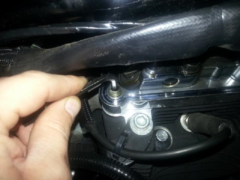 |  |


Remove the inner rocker cover as a unit:
The FSM says to remove and discard the gasket under it.
Another judgment call.
However and depending on the condition of the gasket, it may be reused.
If installing a new gasket, the old one can be stored as a spare.
The inner rocker boxes should be marked (front or rear) to be installed in the same position on installation.
Valve train components must be reinstalled in their original positions during reassembly. 25)
If not, increased engine wear may result.
The rocker arm tips will be worn into the position of the valve stem travel.
The hole for the breather is also threaded on the correct side for installation.
| Be careful when handling the inner rocker box (cover) so that the rocker arm shaft does not slide out. It is held in place by one of the assembly screws and can fall out with the screw removed. 26) 27) |
||
 |  |  |
If the rocker arm shafts do not slip out of the inner rocker by themselves;
You can remove them for inspection by tapping them out with a rubber hammer and a soft metal punch.
Mark which rocker they came from as well as orientation so they can be reinstalled in their original location.