Table of Contents
This is an old revision of the document!

REF: Engine Mechanicals - Sub-07G
Further Study of the Timed Breather Valve
Air / Oil Path Out of the Crankcase
In stock configuration, most all used oil ends up in the flywheel cavity.
A small amount of drain oil from each upper pushrod ball / socket drop to the gearcase then flows to the crankcase thru a hole in the bottom of the cam wall.
While the splash oil to the exhaust valves enters the crankcase through the head drains.
The rotary breather valve functions to relieve crankcase pressure and scavenge oil from the crankcase.
It also controls the flow of oil in the lubrication system.
The breather valve does not pull any oil or air out of the crankcase. Piston downstroke does that.
The breather is nothing more than a window of opportunity for air and oil to escape the crankcase.
It's timed to engine rotation, opens just after piston downstroke and closes after piston upstroke begins.
Piston downstroke provides “pushing power” to usher the oil in the rear oil slot in the case.
The FSM states that it is the flywheels that sends air and oil into the scavenge path to the gearcase.
This isn't the whole story. The oil slot (or galley) is taller than the scraper. Oil has to be “ushered” there by downstroke and wheel motion.
The volume under the pistons on downstroke pushes oil thru the slot to the oil trap at the breather gear.
The wheels alone are not powerful enough to push oil from under the scraper and into the slot pushed against the breather valve.
The flywheel scraper provides forward windage in the crankcase but can't scavenge oil by itself.
Most of wheel windage is above the scraper.
Oil gets behind and under the scraper from gravity as well as the wheels.
Anything that is thick enough on the wheels to be slung off will hit skirts, piston unders, walls, crank bearings etc. and fall below the scraper.
Anything that slides down the wall will fall below the scraper.
Gravity holds it there under the scraper. The wheels are done with it until the oil shows up on the rear end.
The force from downstroke pushes oil to the slot. However, on the that end, higher windage and vacuum CAN pull it back up instead.
The scraper won't stop that and air can only leave thru through the oil trap.
So the scraper keeps oil from perpetually wrapping the wheels.
Piston downstroke pushes both oil from under the scraper to the oil slot and to the oil trap and exhaust air to the oil trap as well.
The breather window is rotated to where the window is exposed to the crankcase area and oil and exhaust air pressure is pushed into the center of the gear.
From there, oil and air is spun out the top of the hollow gear into the gearcase and further oil separates thru stages to lube moving parts on from there.
Opening and closing times of the different breather valves are below but the exact opening-closing points may vary between engines.
As the pistons rise, the breather window is closed and vacuum begins building in the crankcase until the pistons reach TDC.
Then the whole cycle starts over again.
Details in Pictures
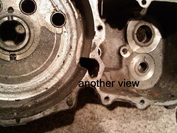
The pics below show the flow from the flywheel cavity to the return pump (applies to 76< only).
- The slot that runs East and West on the rear wall leads to the oil trap near the breather gear.
(oil galley, oil slot, oil passage, maybe other names for it)
That is the way out for both air pressure and pressurized oil from piston downstroke.
- The oil trap is a compartment (or temporary trap) that is sealed off from the gearcase by the breather window being closed.
Both the two different breather windows open after the pistons start decending.
The pistons create positive air pressure before the breather opens (later down the cylinder).
So when the breather opens, oil and air are shot out of the gear faster since the piston has now built up some juice behind.
So air and oil is “trapped” there momentarily by piston pressure during downstroke.
If the breather opens on downstroke, there is 2“ of decent before positive air pressure in created. So in that 2” period, oil can suck back into the crankcase since the air behind is vacuum (negative) . So by not allowing the breather to open at the point of downstroke, the air is turned into what you call air pressure (positive) before the breather opens. Now the oil is pushed out instead of pulled in.
The 57-71 breather creates more vacuum than the 72 gear by closing at (67 deg ABDC). So it's only fitting that they waited until (77 deg ATDC) to OPEN it for the reason above.
They created less vacuum with the 72 breather gear by closing it farther up the cylinder (85-90 deg ABDC). And opened it closer to TDC (20-25 deg ATDC) possibly due to not having that extra vacuum to overcome on downstroke.
There are only 2 areas that get supply (feed) oil pumped to them, the crankpin and the rocker shafts. 1)
Everything else is drain and splash lubed.
XL / XLCH scavenge oil path out the of the crankcase.
| Oil slot. 2) | Half of an oil slot. 3) | Oil trap. 4) |
 |  | 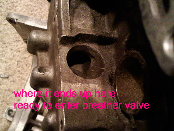 |
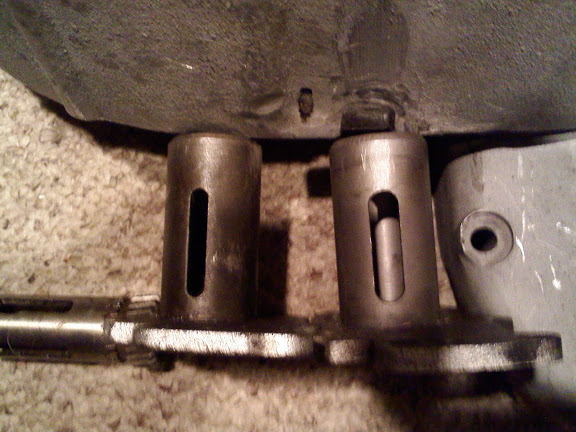
| Another view of the oil trap. 5) | Breather / oil pump installed. 6) | Oil enters the pump here. 7) |
 |  |  |
52-71 XL breather timing:
Opens at 77° after top dead center (ATDC) and closes 67° after bottom dead center (ABDC).
So the window is open for 170° of rotation.
Updates
- Install 72-76 pump.
- Changes breather timing - benefit.
- Modify feed supply.
- Plug old fitting in case.
- Run feed to back of new pump.
72-76 XL breather timing:
Opens 20°-25° after top dead center (ATDC) and closes 85°-90° after bottom dead center (ABDC).
And it's open for 245° (more duration than the 57-71 breather but closes later, less vacuum created).
This is the same as the XR model preferred specs. 8)
72 XR breather timing: (timed off front cylinder) 9)
Standard timing - Opens 14°-16° (ATDC) and closes 85°-90° (ABDC)
Adjust breather timing by adding shims behind the oil pump drive gear (on pinion shaft) and by increasing the slot width in
breather.
Improved timing - Opens at 5° (ATDC) and closes at 105° (ABDC)
Slot in upper cover must be widened to approx. .340“ to make this possible.
Engine has a 1/4 speed oil pump (2:1 ratio).
1975-1980 XR breather timing: (timed off front cylinder) 10)
Engine has a bolt on sump and a 1/4 speed oil pump (2:1 ratio).
Breather valve has been undercut and is not equipped with a timing slot. Breather timing cannot be set on these engines.
1989-2003 XR breather timing: (timed off rear cylinder, 1/2 speed pump) 11)
Engine has a bolt on sump and a 1/2 speed oil pump (4:1 ratio).
Oil pump drive gear re-activated as a breather only.
Oil pump design same as 1975-1980 but with a more efficient gear design and improved oil routing.
Turn rear piston to T.D.C. and line up 0.12” dia. hole in gear shaft with notch in breather sleeve.
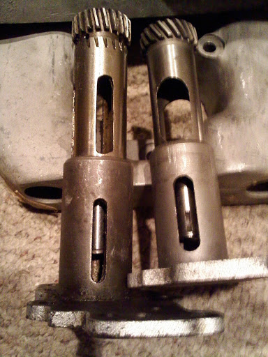
A street oil pump has 2 slots and is driven at 1/2 engine speed. 12)
A racing oil pump has 4 slots and is driven at 1/4 engine speed.
All 4 stroke engines takes two revolutions before you come back to the timing marks being all aligned.
| Left is the unmodified 1/4 speed R valve. Right is the 1000 stock. | R model is the left one. |
 |  |