Table of Contents
This is an old revision of the document!

REF: Engine Mechanicals - Sub-04F
Using / Diagnosing with a Slack Tube (Manometer)
What is a manometer
A manometer is used to measure the pressure difference between two gases, often atmosphere and the gas being tested. 1)
A typical manometer consists of a U-shaped tube half filled with liquid.
The liquid is typically either mercury or water (colored with food coloring for more contrast and easier reading).
The long sides of the tube have a measuring scale marked off in inches or millimeters.
When a gas / air source line is connected to one side of the manometer, the height of the liquid shifts.
The difference in the height of the liquid in each side is used to calculate the source pressure.
Where to get one
A simple U-tube manometer can be homemade made or bought commercially.
Dwyer is a popular brand and these can also be purchased used (Ebay) at a lower price.
Most of the Dwyer tubes have some check valves in the plastic block up top that are supposed to keep them from loosing liquid if the draft changes suddenly. 2)
These check valves have a cork float and a couple of other items that tend to get gunked up and they can make the tube almost impossible to fill.
Many folks strip out the valves and drain the tubes when they are not using them.
The difference in elevation between the two liquid levels is the draft.
You can also buy digital ones with varying degrees of resolution and accuracy.
Here is a 36" Digital Manometer with tubing from Home Depot for $120 (range 0-5 psi, resolution of 0.003 psi and ±0.3% accuracy).
Here is another 36 in. Digital Manometer with tubing for $170 (range of 0-100 psi and a resolution of 0.1 psi)
Crankcase pressure should never reach more than +5 psi either positive or negative.
The higher rated instrument will measure a larger range of differential pressure but you'll lose accuracy measuring the lower pressure from a Sportster crankcase.
The simple U-tube manometer has been noted as the most accurate for this application although the accuracy is in your eyes and hands.
It's simple in construction, low cost, very accurate and sensitive and it can be used to measure other process variables. 5)
However, the drawbacks include fragile construction, high sensitivity to temperature changes and errors can happen while measuring the liquid height.
A simple manometer can be built by partially filling a clear plastic tube with a colored liquid to allow the fluid level to be easily observed.
The tube is then bent into a U-shape and fixed in an upright position.
See also Building your own Slack Tube in the Sportsterpedia.
The levels of the fluid in the two vertical columns should be equal at this point, as they are currently exposed to the same pressure.
This level is therefore marked and identified as the zero reference point of the manometer.
What is it used for
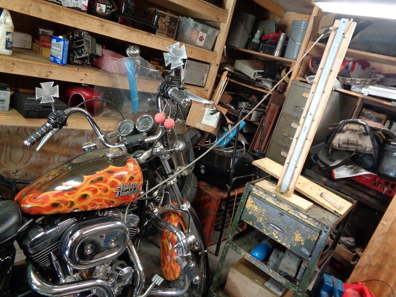
For the purpose of diagnosing Motorcycle issues, a manometer has long been a tool to help in synchronizing the vacuum between multi-carb engines.
With a Sportster having only the one carb, the meter can still be used to measure how much vacuum is present in the venture.
It can also be used to measure crankcase / breather vent pressures.
How tall should the meter be
Generally, whichever liquid media you are using, you want the meter to be tall enough so the liquid doesn't suck back into the engine.
See also Selecting a liquid media below.
If need be, you can get away with using a shorter tube by using a valve to throttle back the source pressure.
In measure crankcase pressure;
You want the vertical leg to be able to the hold actual the pressure differential of water plus an airspace above that.
Else, you could suck the liquid into the engine.
We know of two Sportsters on the XLForum that have been tested for crankcase pressure.
At idle, 15“ of water column has been logged on one leg.
However, the variables are specific to each individual rig.
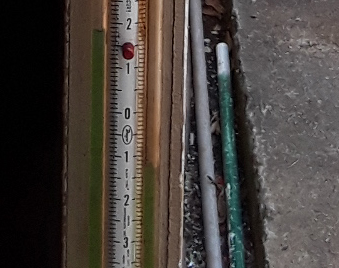
The water level is usually filled to the center of the tubes to allow equal sway up and down the range, but especially the vacuum leg.
Depending on the individual engine, your readings may be higher or lower but a 36” meter is a good starting point for testing crankcase pressure.
With the engine at operating temp and at idle, the vacuum will be the highest.
The reason you need it to be fairly long is because a very slight difference in vacuum can easily cause the fluid to skyrocket especially when using water.
You may need the larger adjustment range.
When the bike is in perfect tune, you may get away with a shorter manometer.
But if your bike is well tuned, you really don't need the manometer.
Selecting a liquid media
The best liquid to use depends on how much pressure you'll be measuring is the short answer.
Typically, mercury or water is suggested.
Mercury has a density of 13,600 kg/m3 whereas water only has a density of 1,000 kg/m3.
Mercury manometers are typically used in high heat applications such as exhaust manifolds.
Liquid manometers measure differential pressure by balancing the weight of a liquid between two pressures.
Light liquids such as water can measure small pressure differences.
Mercury or other heavy liquids are used for large pressure differences.
For an indicating fluid 3 times heavier than water, the pressure measurement range is 3 times greater, but the resolution is reduced.
Typically, there isn't a large amount of crankcase pressure generated in a Sportster engine.
So slight changes that may be important in diagnosing ongoing wear would not be detected with heavier liquids.
Indicating fluids can be colored water, oil, benzenes, bromides, and pure mercury.
When selecting an indicating fluid, check the specifications for specific gravity, operating temperature range, vapor pressure, and flash point.
Corrosive properties, solubility, and toxicity are also considerations.
Liquid characteristics in a U-tube Manometer: 6)
- Viscosity should be low.
- Low surface tension is required.
- The liquid should stick on the walls.
- Should not get vaporized.
How does it work
With the U-tube design, one long tube is mounted vertically on a stand, curved at the bottom center which creates two 'legs' vertically positioned.
This leaves both ends open to atmosphere with the air above the water level having equal pressure in both legs.
One side of the tube is then connected to the pressure source being tested and the other leg is left open to atmosphere.
Once the pressure source is activated, the water moves up or down in each leg indicating where the pressure is headed and the how much.
If the pressure is different between the two ends of the tube, the liquid will move away from the source of greater pressure. 7)
In the drawing to the right, the slack tube represents conditions of atmospheric pressure, then with vacuum and positive pressure applied to the tube. 8)
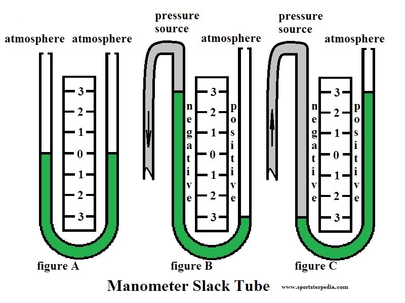
(figure A)
With both legs of the tube open to the atmosphere (or subjected to the same pressure), the liquid maintains the same level in each leg, establishing a zero reference. 9)
(figure B)
With a negative pressure (vacuum) applied to the left side of tube, the liquid rises in the left leg and lowers respectively in the right leg.
(figure C)
As more positive pressure is applied to the negative in the left side of tube, the liquid lowers in the left leg and rises respectively in the right leg.
The engine crankcase pressure cycle begins with the downstroke pushing positive pressure out of the crankcase breather valve(s).
Then on the next upstroke, the breather(s) close and negative pressure builds in the crankcase.
In a perfect world, the same but opposite pressure is then applied during the next downstroke.
However, due to piston ring blowby and other air intake sources, there will be instances where more positive pressure is created.
The increasing positive pressure lowers the total of the negative pressure coming from the source and the tube reflects those changes in pressure.
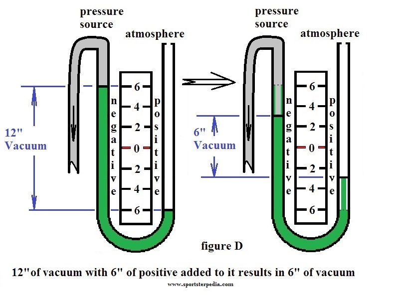 Example (figure D):
A rise in vacuum pressure of 6“ of water (left leg) has a total of 12” in rise as the water has traveled in both legs.
Example (figure D):
A rise in vacuum pressure of 6“ of water (left leg) has a total of 12” in rise as the water has traveled in both legs.
Then a rise in the positive leg of 3“ (6” in actual height) on downstroke still yields a balance of 6“ of vacuum from the engine (showing 3” on left leg).
In this example, the total pressure in the crankcase is still negative but with not as much pressure as was before the last upstroke.
The liquid in the tube may fluctuate slightly with the push-pull of crankcase pressure at cold startup and at hot idle.
The fluctuations should decrease as engine speed rises due to the shorter reaction time of the faster moving pistons.
Until the liquid in the right leg rises above the initial starting point (O reference), the total pressure in the tube exerted out of the engine is still negative even though the pulsations are still present.
Setup and collection of data
- Connect the left side of the manometer tube to a crankcase pressure outlet test port (not the engine breather vents - leave these intact)
The line from the engine / oil tank doesn't have to be clear but a clear line will show any oil mist that escapes but not far out enough to reach the meter.
Allow the liquid to stop moving in the U-tube before measuring. - Record the height of the liquid in the left tube.
From the original 'zero reference', if the height of the liquid has lowered, this measurement is positive.
If the height of the liquid is higher than the start height, this measurement is negative. - Record the height of the liquid in the right tube. Regardless of the liquid rising or falling, this measurement is always positive.
Calculating
The formula for calculating the source pressure is PD = P G H.
Pd = the pressure difference.
P = the density of the liquid in the manometer: mercury equals 13,590 kg/m3 and water equals 1,000 kg/m3.
G = acceleration of gravity: 9.81 m/s2.
H = the height of the liquid in meters.
- Note the beginning point before the meter was hooked to the engine.
The level should be the same on both tube legs. This is noted as the established zero point or (zero reference). - Measure the distance between the liquid's current level on one side and it's zero reference point.
Multiply this distance by 2 since the surface of the liquid on the right goes down by the same distance that the left side goes up.
The total distance the liquid moved is twice the measured movement of one side.
The result is the pressure in water inches. - Convert the non-metric measurements to metric ones. Then, convert the manometer reading to standard units of pressure.
- Use the standard formula p = d * h * 9.8.
“P” is the pressure in pascals.
“D” is the density of the liquid in the tube in kilograms per cubic meter.
“H” is the doubled height difference in meters from step 2.
9.8 is the downward force of gravity, 9.8 meters per second squared.
So if you measure a height difference of .01 meters, double it to .02, multiply by 1,000 kg per cubic meter for water and multiply by 9.8 to get 196 pascals of pressure.
The calculation in step 4 above gives a gauge pressure that is relative to normal atmospheric pressure. 10)
When one side of the tube is open and the liquid is at the same level on both sides, the pressure on the connected side is standard atmospheric pressure.
(14.7 psi or 101.325 kilopacals at sea level)
To determine absolute pressure, you must add standard pressure to your results.
For the above example, the positive pressure of 196 pascals is 196 + 101,325 = 101,521 pascals of absolute pressure.
If your elevation is substantially higher or lower than sea level, get a barometer reading and use its indicated pressure instead of 101.325 kilopascals.
Glossary
Some common terms. 11)
Absolute Pressure.
A measurement referenced to zero pressure; equals the sum of gauge pressure and atmospheric pressure.
Common units are pounds per square inch (psia), millimeters mercury (mmHga), and inches mercury (in.Hga).
Accuracy.
A measure of the closeness of agreement of a reading to that of a standard.
For absolute accuracy, compare to a primary standard (one recognized by NIST).
Accuracies are usually specified as a plus or minus percent of full scale.
Calibration accuracies are often given as plus or minus percent of reading with plus or minus counts.
Ambient Pressure.
The pressure of the medium surrounding a device.
It varies from 29.92 in.Hg at sea level to a few inches at high altitudes.
Atmospheric Pressure.
The pressure of the atmosphere on a unit surface (also called barometric pressure). At sea level, it is 29.92 in.Hg absolute.
Count.
The smallest increment of an A/D conversion that is displayed.
Differential Pressure.
The difference between two measurement points. Common units are inches of water (in.H2O), pounds per square inch (psi), and millibars (mbar).
Display Resolution.
The maximum number of digits on a digital display.
For example, a display resolution of 4½ digits reads a maximum of 19,999 counts; and a display resolution of 5 significant digits reads a maximum of 99,999 counts.
Gauge Pressure.
A measurement referenced to atmospheric pressure. It varies with the barometric reading.
Also used to specify the maximum pressure rating of manometers. Common units include pounds per square inch (psig).
Range.
The region between the lower and upper limits of measurements.
Resolution.
The smallest portion of a measurement that can be detected.
Sensitivity.
The smallest change in measurement that can be detected.
Uncertainty.
An estimate of the possible error in a measurement. This is the opposite of accuracy.
Vacuum.
Any pressure below atmospheric pressure.
When referenced to the atmosphere, it is called a vacuum (or negative gauge) measurement.
When referenced to zero pressure, it is an absolute pressure measurement.
Zero Absolute Pressure.
The complete absence of any gas; a perfect vacuum.