Table of Contents
This is an old revision of the document!

REF: Wheels, Brakes & Tires
Brake System Upgrades
Master Cylinder and Caliper Relationship
Calculating
- First get the area of the master cylinder pistons. The area of a circle is the amount of space the circle covers. 1)
- The formula for calculating the area of a circle is A = πr² where pi (π) equals 3.14 and the radius ® is half the diameter.
- Or 3.14 x (r x r) = piston area (for one piston).
- The pressure is arrived at by Pascals law. 2)
- F (force) = P (pressure) X A (area) or P (pressure) = F (force) ÷ A (area).
- So with a 10 lbs force at the 5/8“ break lever, we get P = 10 ÷ 0.306640625 where P = 32.6 PSI.
You would then multiply 32.6 by the area of the piston in the brake caliper to find the actual pressure applied to the disc by each brake piston.
Front Master Cylinder to Wheel Cylinder Ratio Chart
- General rule of thumb when swapping master cylinders is: 3)
- Bigger M/C = More pressure required to compress brake lever, less lever travel.
The MoCo reduced pressure at the caliper in dual discs systems with a larger master cylinder piston. - Smaller M/C = Less pressure required, more lever travel.
If the area of the master cylinder piston is reduced, the pressure at the caliper increases.
A smaller master cylinder piston used in a dual disc system would make it too easy to lock up the brakes and make for an unsafe system.
Below is a reprint from vintagebrake.com.
4)
While attending Vintage Days West, and thoroughly enjoying it, I was reminded that many of the people I had occasion to talk to, lacked an understanding of the importance of master cylinder to wheel cylinder ratios. This critical ratio is of paramount importance in determining “feel”. It has been my experience that there is a “sweet spot” in the range. I like ratios in the 27:1 range-2 finger power brakes, feeling some line and/or caliper flex. 23:1 is at the other end of the spectrum-firm. Ratios lower than 20:1 can result a feel so “wooden” as to have a toggle switch effect: nothing happens until the wheel locks. Disc and wheel diameters must be taken into consideration. A 10 inch disc working against a 19” wheel just doesn't have the leverage ratio that a 13 inch disc working a 17“ wheel does. The hand lever ratio counts too: witness the adjustable master cylinders from Lockheed and Brembo.
A case in point: I had a complaint from a racer about Ferodo CP901- a compound renown for its great feel. His comment was that they worked poorly until the wheel locked. He had been thrown on the ground twice. Intrigued, I inquired as to the application. “Yamaha RD350” he replied. A red flag went up. CP901 was not available for the 48mm Yamaha caliper. I asked “How that could that be?” He had up-graded his braking system with the 41mm Lockheed unit, but was unaware that a master cylinder change was in order. A stock RD 350 has an already poor ratio of 18.3 :1, and with Lockheed, became an unhealthy 13.3 :1. The “sweet spot” formula said a change to a 11 or 12mm master cylinder was in order: my personal preference and recommendation would have been an 11mm. He was able to switch to a 1/2” , and although not ideal, he was keeping the rubber side down.
For 2 piston opposed calipers, I like ratios in the 27:1 range, feeling some line and caliper flex. For a firmer lever, use 23:1. I think ratios lower than 23:1 produce a lever feel so “wooden” as to have little, if any feel. Combine “low” leverage ratios with sticky pads, and unpredictable lockup is the result. The high effort required at the lever also results in undesired input to the bars. Single piston calipers are much happier in the 14:1 to 12:1 range. Disc and wheel diameters, as well as hand lever ratios, must be considered.
Example for the table below;
Area of a 10mm bore M/C = 78.54 mm² (3.14 x r² (5 x 5, or 25mm) = 78.54).
Area of a 28mm dia. caliper piston = 615.44 mm² (3.14 x r² (14 x 14, or 196mm) = 615.44).
The ratio between the 28mm caliper piston and the 10mm master cylinder is 7.84 to 1, (615.44 / 78.54 = 7.84).
( ) = Number of active pistons. 5)
| Diameter | M/C → | 10mm | 11mm | 12mm | 1/2“ | 13mm | 14mm | 15mm | 5/8” | 16mm | 11/16“ | 19mm |
|---|---|---|---|---|---|---|---|---|---|---|---|---|
| Caliper ↓ | Area-MM² | 78.54 | 95.03 | 113.10 | 126.68 | 132.73 | 153.94 | 176.72 | 197.93 | 201.06 | 239.60 | 283.63 |
| 27mm | 182.25 | 2.32 | 1.92 | 1.61 | 1.43 | 1.37 | 1.18 | 1.03 | 0.92 | 0.91 | 0.76 | 0.64 |
| 27mm (2) | 364.50 | 4.64 | 3.84 | 3.22 | 2.88 | 2.74 | 2.37 | 2.06 | 1.84 | 1.81 | 1.52 | 1.29 |
| 27mm (4) | 729.00 | 9.28 | 7.67 | 6.45 | 5.75 | 5.49 | 4.74 | 4.13 | 3.68 | 3.63 | 3.04 | 2.57 |
| 28mm | 615.44 | 7.84 | 6.48 | 5.44 | 4.86 | 4.64 | 4.00 | 3.48 | 3.11 | 3.06 | 2.57 | 2.17 |
| 28mm (2) | 1231.51 | 15.68 | 12.96 | 10.89 | 9.72 | 9.28 | 8.00 | 6.97 | 6.22 | 6.13 | 5.14 | 4.34 |
| 28mm (4) | 2463.01 | 31.36 | 25.92 | 21.78 | 19.44 | 18.56 | 16.00 | 13.94 | 12.44 | 12.25 | 10.28 | 8.69 |
| 30mm | 706.86 | 9.00 | 7.44 | 6.25 | 5.58 | 5.33 | 4.59 | 4.00 | 3.57 | 3.52 | 2.95 | 2.49 |
| 30mm (2) | 1413.72 | 18.00 | 14.88 | 12.50 | 11.16 | 10.65 | 9.18 | 8.00 | 7.14 | 7.03 | 5.90 | 4.99 |
| 30mm (4) | 2827.44 | 36.00 | 29.75 | 25.00 | 22.32 | 21.30 | 18.37 | 16.00 | 14.28 | 14.06 | 11.81 | 9.97 |
| 32mm | 804.25 | 10.24 | 8.46 | 7.11 | 6.35 | 6.06 | 5.22 | 4.55 | 4.06 | 4.00 | 3.36 | 2.84 |
| 32mm (2) | 1608.50 | 20.48 | 16.93 | 14.22 | 12.70 | 12.12 | 10.45 | 9.10 | 8.13 | 8.00 | 6.72 | 5.67 |
| 32mm (4) | 3217.00 | 40.96 | 33.85 | 28.44 | 25.39 | 24.24 | 20.90 | 18.20 | 16.25 | 16.00 | 13.43 | 11.35 |
| 33mm | 272.25 | 3.47 | 2.86 | 2.41 | 2.15 | 2.05 | 1.77 | 1.54 | 1.38 | 1.35 | 1.14 | 0.96 |
| 33mm (2) | 544.50 | 6.93 | 5.73 | 4.81 | 4.30 | 4.10 | 3.54 | 3.08 | 2.75 | 2.71 | 2.27 | 1.92 |
| 33mm (4) | 1089.00 | 13.87 | 11.46 | 9.63 | 8.60 | 8.20 | 7.07 | 6.16 | 5.50 | 5.42 | 4.55 | 3.84 |
| 33mm (8) | 2178.00 | 27.73 | 22.92 | 19.26 | 17.19 | 16.41 | 14.15 | 12.32 | 11.00 | 10.83 | 9.09 | 7.68 |
| 35mm | 962.12 | 12.25 | 10.12 | 8.51 | 7.59 | 7.25 | 6.25 | 5.44 | 4.86 | 4.79 | 4.02 | 3.39 |
| 35mm (2) | 1924.23 | 24.50 | 20.25 | 17.01 | 15.19 | 14.50 | 12.50 | 10.89 | 9.72 | 9.57 | 8.03 | 6.79 |
| 38mm | 1134.12 | 14.44 | 11.93 | 10.03 | 8.95 | 8.54 | 7.37 | 6.42 | 5.73 | 5.64 | 4.74 | 4.00 |
| 38mm (2) | 2268.24 | 28.88 | 23.87 | 20.06 | 17.91 | 17.09 | 14.73 | 12.84 | 11.46 | 11.28 | 9.47 | 8.00 |
| 38mm (4) | 4536.47 | 57.76 | 47.74 | 40.11 | 35.81 | 34.18 | 29.47 | 25.67 | 22.92 | 22.56 | 18.94 | 16.00 |
| 39mm | 380.25 | 4.84 | 4.00 | 3.36 | 3.00 | 2.86 | 2.47 | 2.15 | 1.92 | 1.89 | 1.59 | 1.34 |
| 39mm (2) | 760.50 | 9.68 | 8.00 | 6.72 | 6.00 | 5.73 | 4.94 | 4.30 | 3.84 | 3.78 | 3.17 | 2.68 |
| 41mm | 1320.26 | 16.81 | 13.89 | 11.67 | 10.42 | 9.95 | 8.58 | 7.47 | 6.67 | 6.57 | 5.51 | 4.66 |
| 41mm (2) | 2640.51 | 33.62 | 27.79 | 23.35 | 20.84 | 19.89 | 17.15 | 14.94 | 13.34 | 13.13 | 11.03 | 9.31 |
| 41mm (4) | 5281.03 | 67.24 | 55.57 | 46.69 | 41.69 | 39.79 | 34.31 | 29.88 | 26.68 | 26.27 | 22.05 | 18.63 |
| 44mm (2) | 3041.07 | 38.72 | 32.00 | 26.89 | 24.01 | 22.91 | 19.76 | 17.21 | 15.36 | 15.13 | 12.70 | 10.73 |
| 48mm | 1809.56 | 23.04 | 19.04 | 16.00 | 14.28 | 13.63 | 11.76 | 10.24 | 9.14 | 9.00 | 7.56 | 6.38 |
| 48mm (2) | 3619.12 | 46.08 | 38.08 | 32.00 | 28.57 | 27.27 | 23.51 | 20.48 | 18.28 | 18.00 | 15.11 | 12.76 |
| 48mm (4) | 7238.25 | 92.16 | 76.17 | 64.00 | 57.14 | 54.53 | 47.02 | 40.96 | 36.57 | 36.00 | 30.22 | 25.53 |
| 50mm | 1963.50 | 25.00 | 20.66 | 17.36 | 15.50 | 14.79 | 12.76 | 11.11 | 9.92 | 9.77 | 8.20 | 6.93 |
| 50mm (2) | 3927.00 | 50.00 | 41.32 | 34.72 | 31.00 | 29.59 | 25.51 | 22.22 | 19.84 | 19.53 | 16.40 | 13.85 |
| 50mm (4) | 7854.00 | 100.00 | 82.64 | 69.44 | 62.00 | 59.17 | 51.02 | 44.44 | 39.68 | 39.06 | 32.79 | 27.70 |
4 Piston Brembo
Rebuilding
No one should be afraid of rebuilding a brake caliper. They are one of the most simple components you will find on a motorcycle.
Two halves, a few pistons and a variety of O-rings. Simply order a rebuild kit for your caliper and buy some fresh brake fluid.
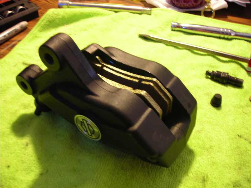
The caliper below is a 4-piston Brembo commonly found on V-rods, Touring models and (in our case) Sportsters which have been upgraded/modified.
The steps listed are roughly the same for a sliding 2-piston caliper with the obvious exception of splitting the caliper halves.
*As always, wear eye protection!
- Drain all the brake fluid from your system.
- Remove the brake line and loosen the bolts which hold the caliper together while it’s still mounted to the bike.
This way you have both hands free and the leverage needed to loosen the bolts. - Now remove the caliper from the fork/swing arm and remove the brake pads.
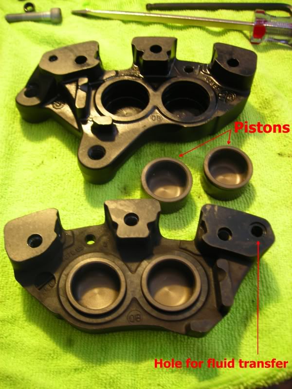
Finish removing the bolts from the caliper, taking care to note which holes they were in.
Lay the two halves out on your work table. - You can remove the pistons with several different methods. One way is to use a spray nozzle attached to an air compressor and shoot air into the fluid transfer holes.
This method can be very effect but also very dangerous. If you aren’t careful you can fire a piston across the shop/garage causing serious injury and/or death (as Harley loves to print over and over in the service manual).
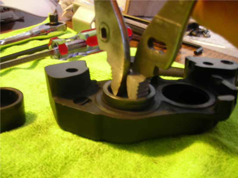
Or you can remove the pistons with either a pair of conventional pliers or reverse/spreader pliers.
To do this with a pair of regular pliers simply take the fastening bolt out and flip the plier handles around backwards.
This allows you to grasp the inside of the piston firmly, then twist while pulling upwards.
The piston can be stubborn to remove at times. - Once all of the pistons have been removed use a wooden pick to remove the O-rings from inside the piston chambers.
There are two for each piston. - Now use parts cleaner/brake cleaner to wash out all of the passages and piston chambers. Towel dry and then allow to air dry.
You should also thoroughly clean and inspect the pistons and piston chambers. The pistons should have a smooth, polished surface.
Small scratches can sometimes be buffed out, if not you must replace the piston.
Nicks and scratches on the piston will tear the O-rings and cause failures. - Once dry you need to lube the O-rings and install them. Rebuild kits usually include a small packet of lubricant grease. If not, use fresh brake fluid.
- Lube and slide the pistons back into their chambers.
- Finally, you can now reassemble the brake caliper, making sure to install the new O-ring in the fluid transfer passage and torque the housing bolts to spec.
That’s it. There’s nothing much to it.
If you don’t already have one go buy a service manual for your bike. They are invaluable.
Non Sportster HD Front Master Cylinders
| Master Cylinder Assembly | Year | Model | Bore | Rebuild Kit(s) | Fluid | Brake Line Fitting / Threads |
| 45010-72 | 1972-1978 | FL FH | 3/4” | 45063-72 | ← Aug '76 DOT 3 → Sept '76 DOT 5 | 1/4“x27 NPSF straight fitting |
| 45010-73 | 1973-1977 | FX | 3/4” | 45063-72 | ← Aug '76 DOT 3 → Sept '76 DOT 5 | 1/4“x27 NPSF straight fitting |
| E1977 | FXS | |||||
| 43306-78 | L1977-1978 | FXS | 3/4” | 45063-72 | DOT 5 | 90° fitting |
| 1978 | All FX | |||||
| 45013-72 | 1979 | FXS FXS-80 | 3/4“ | 45063-72 | DOT 5 | 90° fitting |
| 1980-1981 | All FX | |||||
| Replacement for 45010-72 master cylinder on 1972-1981 FL w/ straight fitting. | ||||||
| 45020-79 | 1979 | FXE FXEF FXEF-80 | 3/4” | 45063-72 | DOT 5 | 90° fitting |
| 45013-82 | 1982-1984 | FLH-80 Classic | 3/4“ | 45063-82A | DOT 5 | 3/8”x24 |
| 45013-82A | 1982-1983 | FX models | 3/4“ | 45063-82A | DOT 5 | 3/8”x24 |
| 45019-84 | 1984 | FXST | 5/8” | 45072-87 | DOT 5 | 7/16“x24 |
| E1985 | All FX | |||||
| 45019-85 | 1984-1986 | FX models | 5/8“ | 45072-87 | DOT 5 | 7/16”x24 |
| 45013-85A | 1987-1990 | FLT | 11/16“ | 45006-87A | DOT 5 | 3/8”x24 |
| 1987-1990 | FXRT FXRS-SP FXRS-CON |
|||||
| 45019-85A | 1987-1990 | FXR FXRS FXLR | 5/8“ | 45072-87 | DOT 5 | 7/16“x24 |
| 1987-1990 | Softail | |||||
| 1991 | FXDB | |||||
| 1991-1992 | FXR FXRS FXLR |
|||||
| 1991 | Dyna FXDB-S | |||||
| 45013-85B | 1991-1992 | All FLT FXRT FXRS-SP FXRS-CON | 11/16” | 45006-87A | DOT 5 | 3/8“x24 |
| 1992 | All Dyna | |||||
| 45013-85C | 1992 | FXDB FXDC | 11/16” | 45006-87B | DOT 5 | 3/8“x24 |
| 45013-93 | 1993-1994 | FXRS-SP FXRS-CON | 11/16” | 45006-87A | DOT 5 | 3/8“x24 |
| 1993-1995 | All FLT | |||||
| 1995 | FXDL | |||||
| 1995 | FXDS-CON | |||||
| 45019-93 | 1993-1994 | FXR FXLR | 5/8” | 45072-87 | DOT 5 | 7/16“x24 |
| 1993-1995 | All Softail FXDWG |
|||||
| 1995 | FXD | |||||
| 45013-96 45013-96D | 1996 | All FLT | 11/16” | 45072-96 45072-96A 45072-96C | DOT 5 | 3/8“x24 |
| 1996 | FXDL | |||||
| 1996 | FXDS-CON | |||||
| 45019-96 45019-96D | 1996 | All Softail | 9/16” | 45006-96 45006-96A 45006-96C | DOT 5 | 7/16“x24 |
| 1996 | FXDWG | |||||
| 1996 | FXD | |||||
| 45019-06A | 2007 | FXD FXDL FXDWG FXDC FXDB FLSTSC FXST FLSTC FLSTF FXSTB FXSTD FLSTN FXSTC | 9/16“ | 45006-96C | 7/16”x24 | |
| 45019-08 | 2008 | FXDWG / Anv | 9/16“ | 45006-96C | 7/16”x24 | |
| 2008-2009 | FXD FXDL FXDC FXDB FXST FLST FLSTC FLSTF FXCWC FXSTB FXSTC FLSTN FLSTSB |
|||||
| 45064-08 | 2008-2009 | FXCW | 9/16“ | 45006-96C | 7/16”x24 | |
| 45170-08 | 2008-2009 | FXDF | 11/16“ | 45072-96C | 7/16”x24 | |
| 44551-08 | 2008 | FLHR FLHTCU FLHTC FLHRC FLTR FLHT FLHX | 15mm | 42862-06A | 10mm x 1 | |
| 42057-09 | 2009 | FXSTSSE3 | 11/16“ | 45072-96C | 3/8”x24 | |
| 45019-08A | 2008 | FXST FLST FLSTC FLSTF FXCWC FXSTB FXSTC FLSTN FLSTSB | 9/16“ | 45006-96C | 7/16”x24 | |
| 2010 | FXD FXDL FXDC FXDB FXDWG FXST FLSTC FLSTF FLSTN FLST FXCWC FXSTC FLSTSB FLSTFB |
|||||
| 45170-08A | 2010 | FXDF | 11/16“ | 45072-96C | 3/8”x24 | |
| 41700233 | 2015-2016 | FXSB / 103 FLSTC / 103 FLSTF / 103 FLSTN / 103 FLSTFB / 103 FLS / 103 FXST | 7/16“ | 41700087 | 10mm | |
| 2016 | FLS | |||||
| 45029-11C | 2016-2017 2016-2017 2016 2016 2016 2016 | FXDWG / 103 FXDB / 103 FLD / 103 FXDBP 103 FXDBC / 103 | 9/16” | 45006-96E | 3/8“x24 | |
| 45170-08D | 2016-2017 | FXDL / 103 FXDF / 103 | 11/16” | 45072-96D | FXDB FXDB103 FXDBP103 7/16“x24 All Others 3/8”x24 |
|
| 41700451 | 2-16 | FLSS FLSTFBS | 7/16“ | 41700087 | 10mm | |
| 41700456 (black) | 2017 | FXDLS | 11/16” | 45072-96D | 3/8“x24 | |